

A transformer specification for an artificial intelligence (AI) data center should describe the load changes that reach the transformer terminals, not assume that every computing workload fluctuation appears unchanged at the upstream supply. Uninterruptible power systems (UPS), power supplies, local storage and controls can modify the electrical demand. The enquiry needs amplitude, duration, repetition and source conditions so voltage response and thermal duty can be assessed separately.
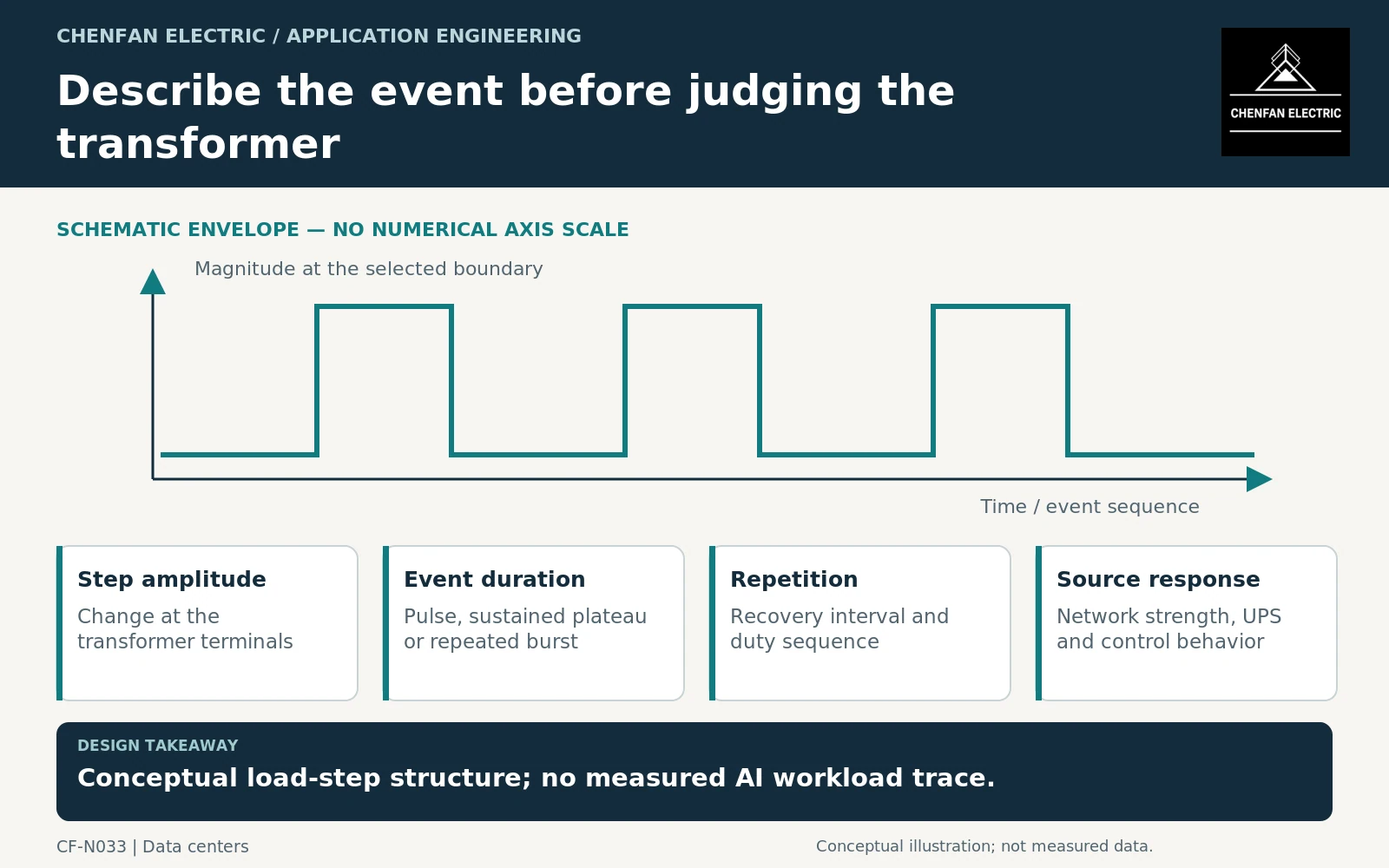
Establish the measured or modeled boundary
Identify whether the load trace represents server direct current (DC) consumption, rack alternating current (AC) input, UPS output or transformer-side demand. These traces are not interchangeable. State the aggregation interval and whether the data are measured, forecast or derived from a model.
A UPS performance standard addresses the UPS’s defined operating behavior and testing. It does not prove how a particular AI workload will propagate through every facility architecture. [1]
Avoid importing a dramatic single-rack peak into a whole-site transformer requirement without an aggregation basis. Conversely, coarse facility averages may hide a coordinated event that matters to voltage response. The data selection should match the engineering question.
Separate electrical response from accumulated heating
A brief current change can influence voltage before it materially changes bulk transformer temperature. Repeated or sustained loading affects the thermal sequence. One assessment cannot replace the other simply because both begin with a load trace.
General transformer application guidance addresses voltage variation and loading considerations. Equipment-specific loading guides provide a framework for thermal assessment using the relevant ambient and duty assumptions. [2] [3]
An illustrative trace might rise from 60% to 90% of an agreed current base for ten seconds, repeat every minute and then remain at 75%. These are hypothetical values defining a study case, not measured AI demand. The percentages require a stated current base and terminal voltage before they can be used quantitatively.
Specify the event dimensions that matter
| Event field | Information to retain |
|---|---|
| Baseline and step | Absolute current or P-Q values at a named boundary |
| Rise and fall behavior | Appropriate time resolution and waveform assumptions |
| Duration | Temporary pulse or sustained operating state |
| Repetition | Frequency and recovery interval |
| Source condition | Utility, generator or alternate configuration |
| Mitigation state | UPS or storage controls active during the event |
Include relevant reactive-power and harmonic behavior rather than treating the step as purely active power by default. Any simplification should be documented and checked for its effect on the conclusion.
Ask for a coordinated response, not a generic oversized unit
Increasing transformer MVA may change some system characteristics, but it is not a universal cure for voltage disturbances. Source impedance, cable impedance, control response and the load’s own tolerance remain part of the problem.
The study should state the acceptance boundary: allowable equipment operation, voltage behavior at specified buses, thermal duty or another agreed criterion. It should not claim that a transformer alone guarantees uninterrupted information technology (IT) operation.
For procurement, issue the representative trace, bounding cases, source configurations and model assumptions. Ask the transformer supplier to provide the parameters required for the coordinated study and to confirm the resulting duty. The useful specification is a reproducible electrical event description, not the phrase “AI-ready transformer” or an unsupported multiplier applied to server power.
Core procurement checkpoint: Translate rapid load changes into the right design inputs
A computing-load step is not itself a core flux-density specification. Ask the transformer designer to distinguish the resulting current duty from any voltage or frequency excursion relevant to excitation. For a core order, retain the approved magnetic design and request only the test records that have been agreed. Do not promise power-quality or ride-through performance from the choice of CRGO alone.
For the core enquiry: Approved voltage-frequency basis; controlled core drawing; loss-test conditions; responsibility for dynamic equipment and system validation.