

A wind farm’s reactive-power obligation should be allocated across the converters, collector network, transformers and compensation equipment. The required value at the point of interconnection is not automatically the reactive duty of each turbine transformer or the main grid transformer. Use a common load-flow and control basis to determine the quantities at each equipment boundary.
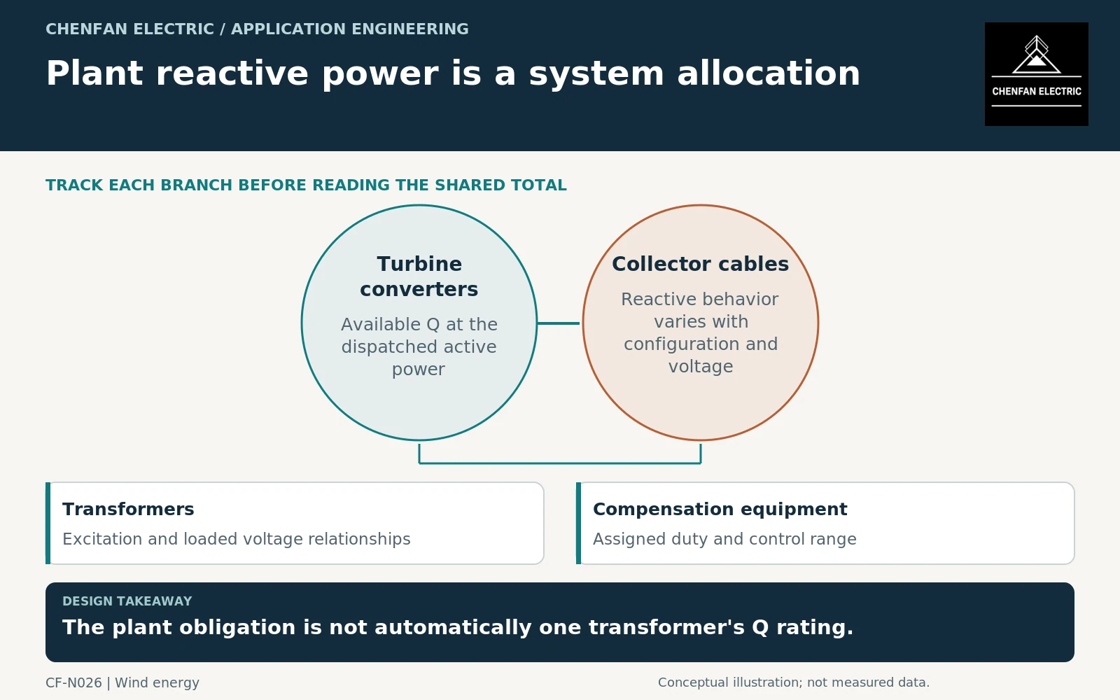
Fix the reference point and sign convention
State where the plant requirement is assessed and how reactive import and export are signed. Identify metering locations and the voltage range associated with the obligation. A converter-terminal capability statement cannot be compared directly with a grid-interface requirement without accounting for the intervening network.
Manufacturer documentation for meter-point reactive-power control illustrates that regulation can be organized around a designated measurement point. Such documentation describes a particular implementation; it does not define the control architecture of every wind project. [1]
The project’s control design should identify the regulated quantity, participating devices and operating restrictions. Keep contractual plant requirements separate from equipment capability and installed controller settings.
Determine each contribution through the network model
Cable charging, transformer excitation and loaded network behavior affect the reactive balance. Their combined effect changes with voltage, topology and operating power. The sign and magnitude at one point cannot be inferred by adding equipment brochure maxima without a network model.
Transformer application guidance addresses voltage variation and operating conditions. Wind-turbine transformer requirements apply to their defined equipment class, not automatically to the entire plant’s main grid interface. [2] [3]
Review full production, low production, relevant nighttime states and credible collector outages. Long cables can remain electrically significant even when active generation is low. Do not assume that zero active output means zero reactive-power coordination work.
Allocate duties without double counting capability
| Equipment | Allocation question |
|---|---|
| Turbine converters | What Q remains available at the required P and voltage? |
| Turbine transformers | What winding currents result from those converter states? |
| Main grid transformer | What combined P-Q and tap cases occur? |
| Compensation plant | Which residual duty and response are assigned to it? |
| Plant controller | How are limits and priorities coordinated? |
A converter’s maximum reactive capability may reduce its available active power within a current limit. If the plant obligation assumes both maxima simultaneously, obtain evidence that the combination is actually permitted.
Avoid counting the same compensating resource twice—once as turbine capability and again as an independent plant reserve. The allocation should identify which devices are available in each normal and outage case.
Convert the allocation into equipment schedules
Each transformer enquiry should receive its own terminal P-Q cases, voltages, durations and tap assumptions. The compensation specification should receive its assigned range and control role. The plant controller specification should receive the coordinated priorities and unavailable-device behavior.
Where the loading schedule creates sustained current, assess the appropriate thermal duty rather than treating reactive power as harmless because it does not represent exported active energy. Mineral-oil loading guidance provides one equipment-specific framework. [4]
The final review should reconcile the plant requirement with the sum of modeled equipment behavior at the correct boundary. A well-allocated specification explains which device provides which service, under which conditions, and what limitation remains when part of the plant is unavailable. That is stronger evidence than requiring every transformer to “meet the wind-farm power factor” without defining where or how.
Core procurement checkpoint: Do not convert reactive-power allocation directly into core area
The system study allocates reactive duties; the transformer designer then determines the magnetic and winding design for the relevant cases. A core enquiry should use that approved result, with voltage and frequency assumptions recorded separately from the MVAr schedule. Neither a compensation rating nor a CRGO grade establishes the complete transformer’s reactive capability or the plant’s voltage-control performance.
For the core enquiry: Approved magnetic design; voltage-frequency cases; core drawing; material specification; agreed loss and inspection conditions.