

The choice between a nacelle, tower-base or external wind-turbine transformer location changes the mechanical, cooling and maintenance interfaces even when the electrical rating is similar. Select the location together with the turbine arrangement and replacement strategy. A transformer that fits one location electrically may require substantial redesign to function in another.
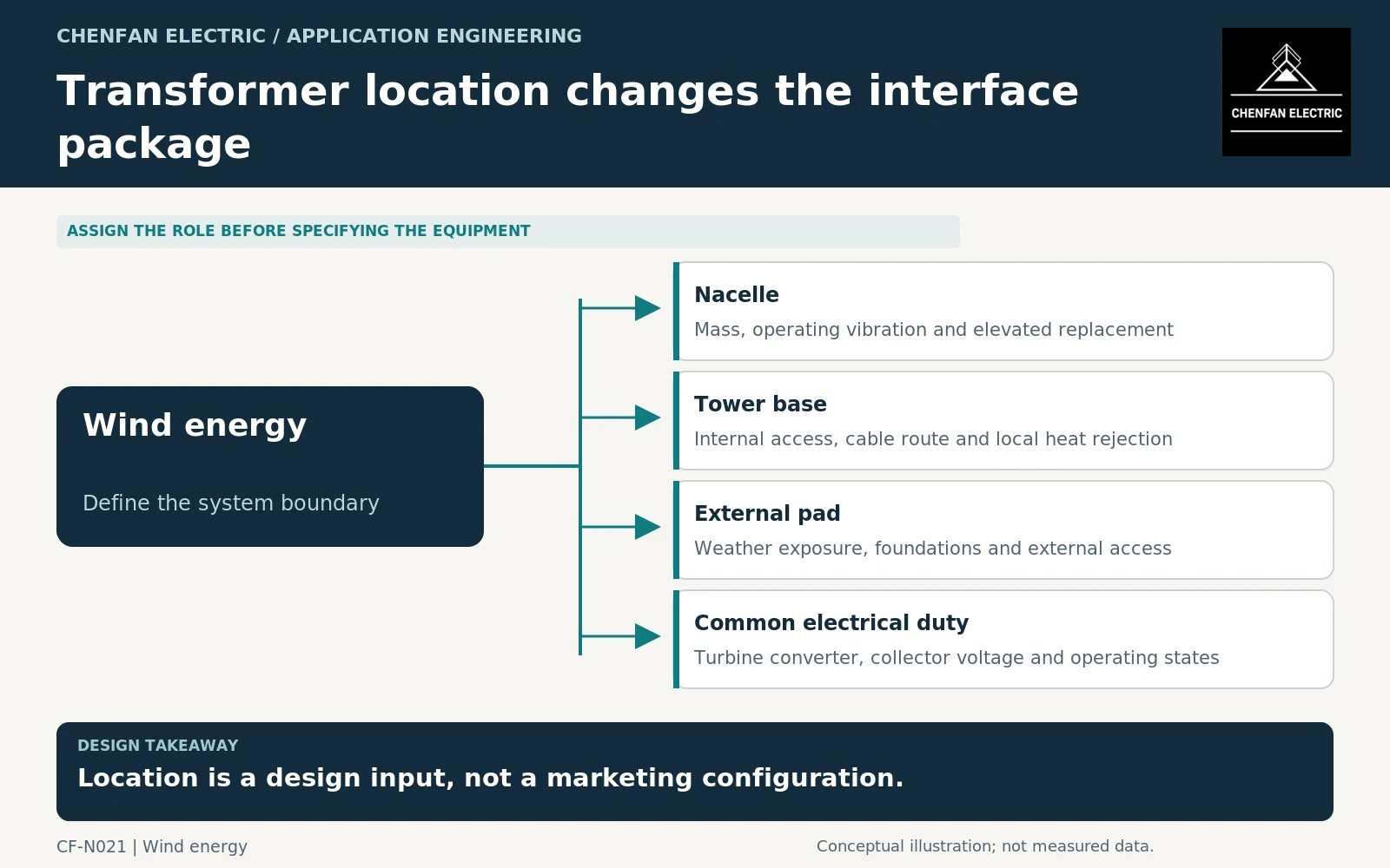
Define the actual turbine boundary
Identify whether the transformer connects a turbine converter to the collection network or serves another plant function. IEC/IEEE 60076-16 addresses a defined class of wind-turbine step-up transformers, including an upper limit on winding highest voltage for equipment. Its scope should not be extended automatically to every transformer in a wind farm. [1]
The enquiry should include converter data, collector voltage, winding arrangement and operating duty before comparing locations. Otherwise, a mechanical preference may conceal a different electrical architecture or cable-current requirement.
Nacelle placement adds elevated interfaces
A nacelle installation must fit the turbine’s mass allocation, support arrangement, operating vibration environment and thermal design. The transformer can interact with surrounding equipment through both heat and structural loads. These interfaces need supplier-approved inputs rather than generic statements that the unit is compact.
Replacement is especially important. Record the removal configuration, component masses, access openings and interfaces with the turbine’s handling strategy. This is a requirement for coordinated engineering, not a recommendation to improvise lifting arrangements at height.
The nacelle’s air or liquid cooling system must also provide the conditions used in the transformer assessment. Outdoor air temperature alone does not establish the temperature of recirculated air or a shared cooling medium.
Tower-base placement changes, rather than removes, constraints
At the tower base, service access may be more direct, but internal dimensions, door openings, cable bends and ventilation can still dominate the arrangement. Include the route from the transformer to its external removal point after all permanent equipment is installed.
Longer internal electrical paths can change the cable and connection interfaces. The electrical designer should compare these paths using the same operating cases, rather than assuming that moving the transformer downward has no effect outside the equipment footprint.
A tower-base enclosure may have a different humidity and temperature cycle from the nacelle. Define the local installation conditions, including shutdown periods, rather than applying one environmental description to the entire turbine.
External placement shifts exposure and access
An external unit can separate transformer heat from the tower interior, but it adds weather, foundation, enclosure and external connection requirements. Access may improve only if roads, working space and removal routes remain available throughout the operating life.
| Location | Interface that must not be omitted |
|---|---|
| Nacelle | Operating structural loads and elevated replacement |
| Tower base | Internal service envelope and ventilation path |
| External | Site exposure, foundation and external cable interfaces |
The cited fan and insulating-liquid-to-water heat-exchanger standards address accessories of liquid-immersed power transformers and reactors, not all dry-type cooling arrangements or the complete turbine cooling system. Confirm who guarantees the supplied inlet conditions and who responds when cooling becomes unavailable. [2] [3]
Compare complete installation packages
Require each option to include the same electrical duty, connection scope, cooling responsibility and replacement boundary. General transformer application guidance supports reviewing connections and operating conditions, but it cannot choose the turbine layout in isolation. [4]
The decision record should state why a location is preferred and which constraints it creates elsewhere. A useful comparison may favor lower elevated mass, shorter high-current connections, easier replacement or reduced enclosure heat. It should not claim all benefits without accounting for their associated interfaces.
Core procurement checkpoint: Translate installation location into a controlled interface
A nacelle, tower-base or external transformer location should be reflected in the equipment manufacturer’s approved core and support arrangement. For core procurement, record mass and dimensional limits, supplied clamp boundaries and assembly access rather than relying on the wind-turbine application label. Any vibration or installation qualification must refer to the relevant tested configuration, not simply to the electrical-steel supplier.
For the core enquiry: Core outline and mass requirement; clamp responsibility; installation envelope; handling state; approved drawing and qualification boundary.