

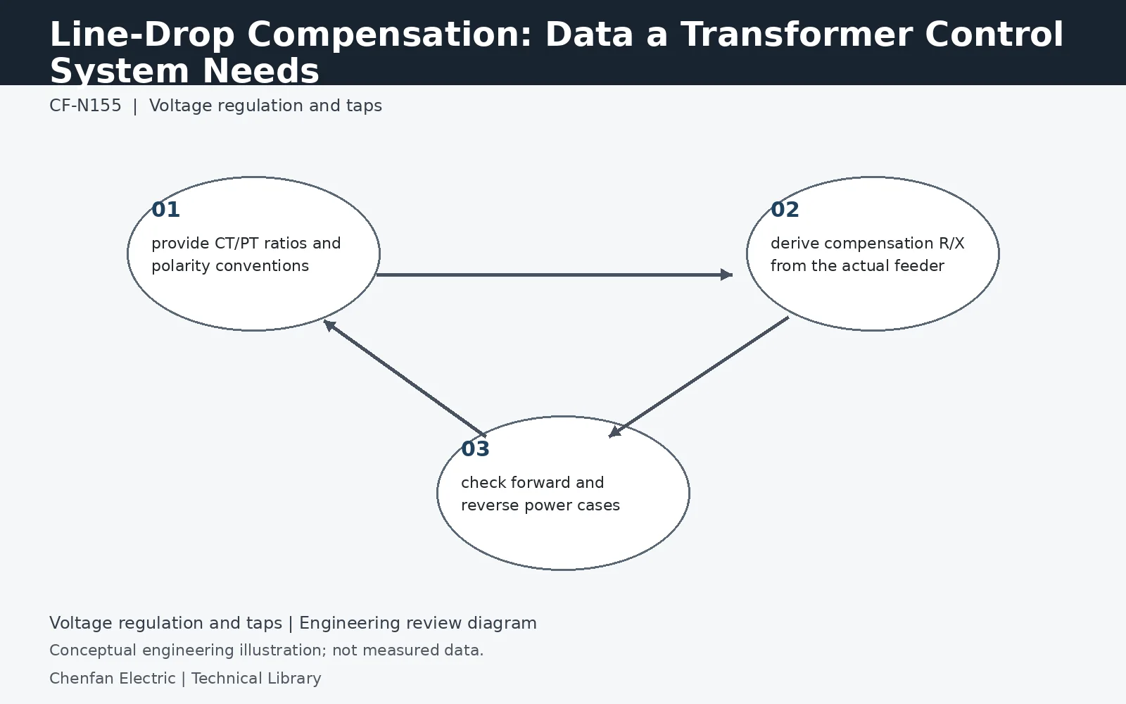
Line-drop compensation estimates remote-bus voltage from local voltage and current measurements plus an assumed feeder impedance. Its quality therefore depends on CT/PT scaling, feeder R and X, load direction and the control sign convention. A compensation setting copied from another feeder can be wrong even if the transformers are identical. The study should also consider reverse power and topology changes.
Start with a phasor estimate of the remote node
For current defined from the transformer toward the load, a simple feeder model gives Vremote = Vlocal − I(R + jX). The voltage and current must be on compatible phase and ratio bases. A controller may express its compensation parameters in secondary volts, ohms or normalized units, so the primary feeder values cannot be entered blindly. Record the exact scaling and sign convention from the controller documentation alongside the approved feeder model.
One current measurement may not represent all downstream loads
A single equivalent feeder impedance works best when the monitored current follows the represented path. Distributed loads, branching feeders or generation between the transformer and the target bus complicate that assumption. The current at the transformer can differ from the current through the final section near the remote point. Validate the estimated voltage against a multi-node load-flow model or suitable measurements across representative states rather than tuning compensation to one operating snapshot.
Revisit compensation when flow or topology changes
Reverse power changes the direction of the calculated drop, while a bus transfer can change the physical impedance being represented. Define which controller mode is valid in each condition and how an invalid or uncertain state is handled. Compare predicted and measured remote voltage with timestamps, tap position and feeder configuration retained together. A transformer replacement may leave the feeder model unchanged, whereas a cable reconfiguration can invalidate it even when the transformer remains the same.
Technical reference framework
[1] IEC 60076-8:1997 — Application guide.
[2] IEC 60214-1:2014 — Tap-changers, Performance requirements and test methods.
[3] IEEE C57.131-2024 — Tap-changers, Performance requirements and test methods.