

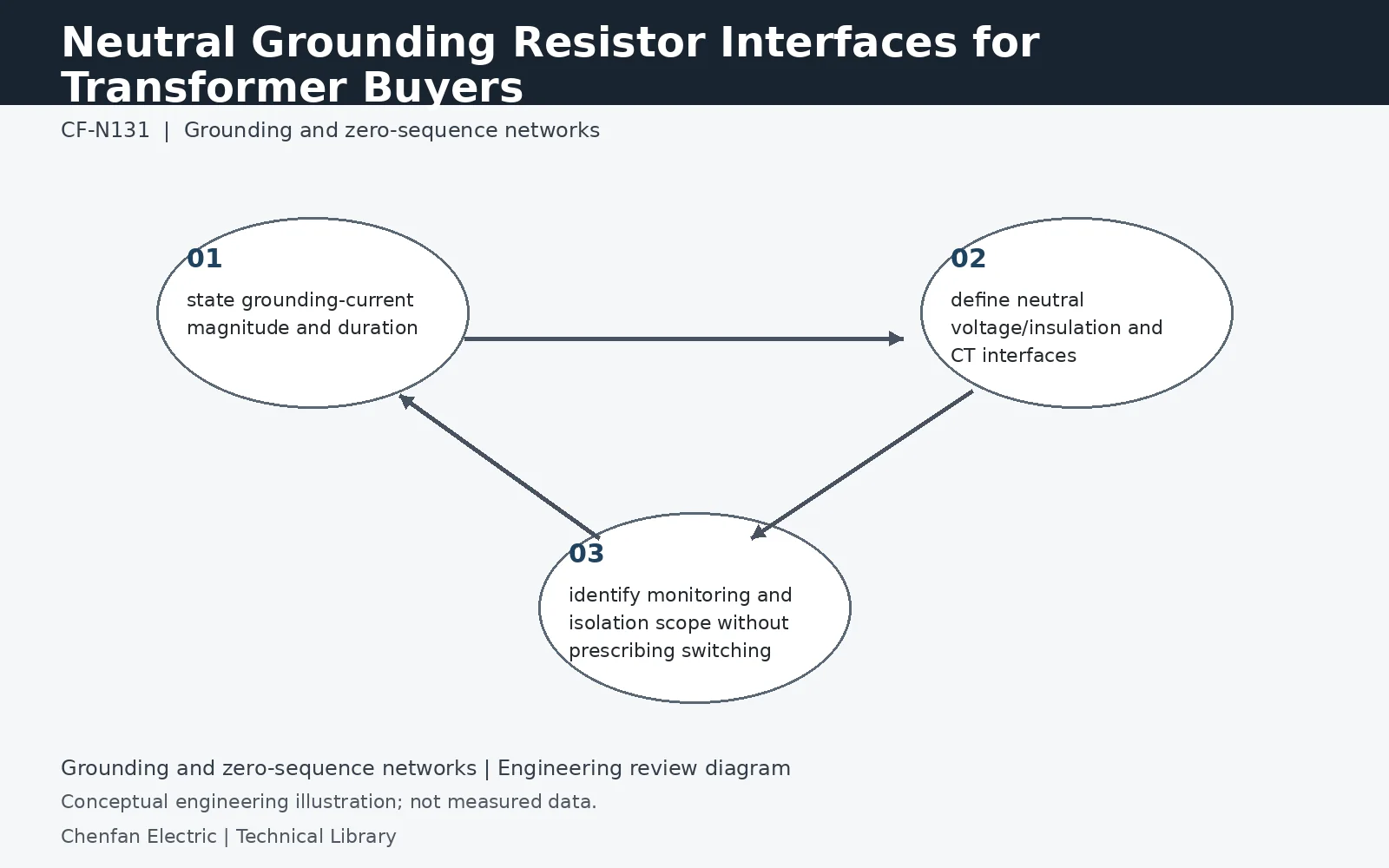
A neutral grounding resistor interface must be specified from the fault study backward. The transformer neutral terminal, bushing, lead and CT arrangement must withstand the specified grounding current and duration, while the resistor must see the correct system voltage. Procurement should also define neutral insulation, CT ratios/classes, monitoring contacts and whether the connection includes a disconnecting or earthing device—without treating any of these as field switching instructions.
Size the resistor on the correct voltage basis
For an illustrative 11 kV system, the nominal phase-to-neutral voltage is 11/√3 = 6.35 kV. If a directly connected neutral resistor dominates the earth-fault impedance, a 400 A target gives approximately 6,350/400 = 15.9 ohms. This is a circuit estimate, not a selected product rating. Include the source sequence impedances, resistor tolerance and hot resistance in the actual calculation. A resistor connected through a grounding transformer requires the appropriate ratio conversion; its secondary voltage is not the system phase voltage.
Carry one fault duty through every neutral component
Specify the current, clearing duration and permitted repeat duty together. A resistor rated for a brief fault does not establish the withstand of the neutral lead, bushing, disconnect or CT primary conductor. Conversely, an adequately rated neutral terminal does not establish resistor thermal capacity. The transformer and resistor suppliers should work from the same duty schedule, including the backup-clearing case and initial operating temperature. Identify which party verifies each interface rather than leaving the assembled neutral circuit without an owner.
Locate the CT and monitor the complete connection
Draw the neutral-to-resistor conductor, CT location and connection to the station earth system. This establishes what the relay actually measures and whether any parallel return bypasses that measurement. Separate an overtemperature alarm from loss-of-continuity detection: one does not automatically provide the other. The purchase specification should identify available contacts, auxiliary supply, communication points and the response expected from the protection designer. Monitoring cannot compensate for an unapproved change in the primary grounding arrangement.
Technical reference framework
[1] IEC 60076-8:1997 — Application guide.
[2] IEC 60076-1:2011 — Power transformers, General.
[3] Post Glover NG112-06 — Neutral grounding resistors: Technical information.
[4] Post Glover GT210-10 — Neutral grounding resistors with transformer.