

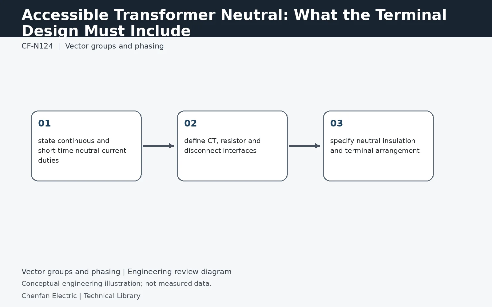
An accessible neutral is an electrical and mechanical interface, not just a schematic symbol. The terminal must be rated for the expected continuous, harmonic and fault current; insulation level and bushing arrangement must match the grounding scheme; and provision may be needed for CTs, grounding resistors, disconnecting links or surge protection. Procurement should define these interfaces before the tank and lead arrangement is frozen.
Define the current paths the neutral must carry
State continuous unbalance, expected harmonic current and short-time ground-fault current separately, with duration for the latter. A neutral rated only for a short grounding duty is not automatically suitable for continuous nonlinear single-phase load. Conversely, a large continuous-current terminal does not by itself establish the required short-time thermal and mechanical withstand. Follow the path from winding star point through internal lead, bushing, link, CT region and external conductor. The weakest applicable component can limit the interface.
Reserve space for measurement and maintainable connections
A neutral CT may require a defined conductor arrangement, polarity orientation, insulation clearance and accessible secondary terminal box. Its location also determines the boundary of restricted earth-fault protection. Provide the grounding resistor or reactor connection geometry and any specified removable link before the lead design is finalized. Mechanical space for a CT does not prove that the conductor passes through the intended protection zone. Review the layout and the protection schematic together, including how external connections avoid bypassing the measured path.
Match neutral insulation to the grounding study
The neutral may be at a low potential during normal operation yet experience displacement or transient voltage under a fault or changed grounding state. Specify its insulation level from the actual grounding and overvoltage assessment, not from an assumption that “neutral means zero volts.” Confirm whether reduced neutral insulation restricts allowable operating configurations. Retain the approved terminal drawing with the grounding equipment data sheet. Any later move from solid to impedance grounding can change the electrical duty even if the external terminal still physically fits.
Technical reference framework
[1] IEC 60076-8:1997 — Application guide.
[2] IEEE C57.105-2019 / Cor 1-2023 — Three-phase transformer connections.
[3] Post Glover GT110-08 — Zig-zag grounding transformers.