

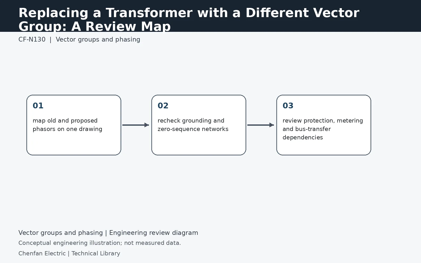
Changing vector group during replacement is a system change, not a catalog substitution. Review phase displacement, grounding path, zero-sequence transfer, neutral availability, differential-protection compensation, metering references, bus ties and any downstream rotating-machine or converter phasing. If any parallel or transfer path can connect old and new sources, phase compatibility must be resolved before the replacement specification is issued.
Classify the change before comparing ratings
A new connection symbol can alter angular displacement, neutral availability or both. Mark exactly which features change between the existing and proposed transformer. Matching voltage and kVA does not resolve those differences. An apparently independent downstream bus may still have a maintenance tie, standby generator or converter reference connected elsewhere. Trace those interfaces on the current one-line and phase-reference drawings rather than using the original installation diagram without checking later modifications.
Grounding changes need their own fault model
Replacing a delta-side interface with a grounded-star interface can change the zero-sequence network and ground-fault contribution. Removing an accessible neutral can eliminate an intended grounding or measurement path. Check neutral insulation, grounding equipment, CT positions and earth-fault protection together. The resulting fault-current change may also affect downstream coordination. A phase-angle correction in a relay does not restore a missing physical grounding path, so protection configuration and primary-system compatibility must be resolved as separate tasks.
Release a coordinated change package
The approved package should contain the revised connection and phasor drawings, permitted source states, relay/metering changes and commissioning acceptance criteria. Identify any operating state that must remain prohibited until the modification is complete. Obtain the transformer and affected equipment suppliers' confirmation where their interfaces change. Do not describe the result as a drop-in replacement unless all relevant interfaces have actually been resolved. Preserve the superseded diagrams for traceability while ensuring the operating team receives one clearly identified current version.
Technical reference framework
[1] IEC 60076-8:1997 — Application guide.
[2] IEEE C57.105-2019 / Cor 1-2023 — Three-phase transformer connections.