

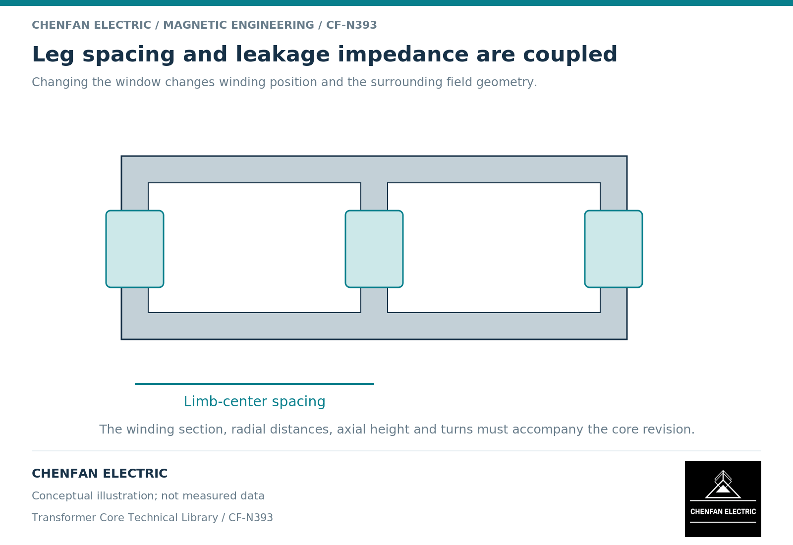
Core leg spacing affects the space available for windings and their relationship to neighboring limbs, but it does not determine leakage impedance by itself. Leakage behavior depends on the winding geometry, connection and spatial distribution of ampere-turns. A leg-spacing change is therefore a coupled electromagnetic design question rather than merely a dimensional adjustment.
Identify which geometry actually changes
Increasing the distance between limbs may enlarge the window, alter winding clearance to adjacent structures or permit a different winding arrangement. It does not necessarily change the radial gap between a particular pair of concentric windings. Those are separate dimensions.
Transformer design treatments relate leakage effects to incomplete winding linkage and the field energy associated with the winding arrangement. [1] A single center-to-center core dimension cannot represent that entire geometry.
Record winding height, radial build, interwinding spacing, axial alignment, turn distribution and lead arrangement alongside leg spacing. Without these inputs, two “same spacing” designs can still have different leakage impedance.
Compare leakage energy on a consistent basis
For a suitable linear equivalent representation, magnetic energy associated with a specified current can be related to an inductance. The exact interpretation requires the winding reference, excitation constraints and treatment of mutual coupling to be stated.
Finite-element methods can evaluate field energy and related quantities, but the chosen geometry and boundary conditions determine what is included. [2] A model of one window may omit neighboring-phase and end-region effects important to another design.
Do not compare an inductance referred to one winding with an impedance percentage based on another rating without the required conversion. Frequency, base power and base voltage also belong to the reporting definition.
Use a controlled design comparison
| Quantity | Comparison rule |
|---|---|
| Core spacing | Identify the exact dimension changed |
| Winding dimensions | Hold fixed or record their deliberate revision |
| Current and connection | Use the same reference and operating case |
| Leakage output | State inductance, reactance or impedance definition |
| Structural exposure | Check affected clamps, tank and leads |
| Dielectric layout | Preserve required clearances and insulation geometry |
A useful first comparison changes only leg spacing where physically meaningful. A second compares the fully reoptimized active parts. These answer different questions: sensitivity to one dimension versus the performance of two complete candidate designs.
If the spacing change is made solely to solve assembly clearance, the electrical designer should still determine whether the resulting field changes are negligible. The answer should be documented rather than assumed.
Separate design intent from manufacturing tolerance
The nominal spacing selected by the designer and the permitted manufacturing variation around it are not the same issue. The former may establish a different active-part geometry; the latter is a controlled variation within an approved design.
The core manufacturer should receive the released spacing, tolerances and reference datums. It should not infer an allowable redesign from a tolerance band or independently change spacing to make a winding fit.
The final change review should retain the affected geometry, electrical comparison and interface checks. This makes it possible to say precisely whether a spacing revision changes leakage performance, merely changes available space, or requires a broader winding redesign. None of those conclusions follows from leg spacing alone.
References
[1] Lloyd Dixon / Texas Instruments. Magnetics Design 4 – Power Transformer Design.
[2] David Meeker. Finite Element Method Magnetics User Manual.