

Volts per turn links the winding definition to the core’s magnetic duty. It must be based on the voltage induced in the relevant winding, the waveform and frequency, and the net magnetic area. A rule based only on nameplate line voltage can be wrong when connection, tap position or internal voltage drops are ignored.
Begin with the voltage integral
For an ideal winding linking a common flux, induced voltage is e(t) = N dΦ/dt. Integrating gives the change in flux linkage. This is the general starting point; a sinusoidal formula is a special case. [1]
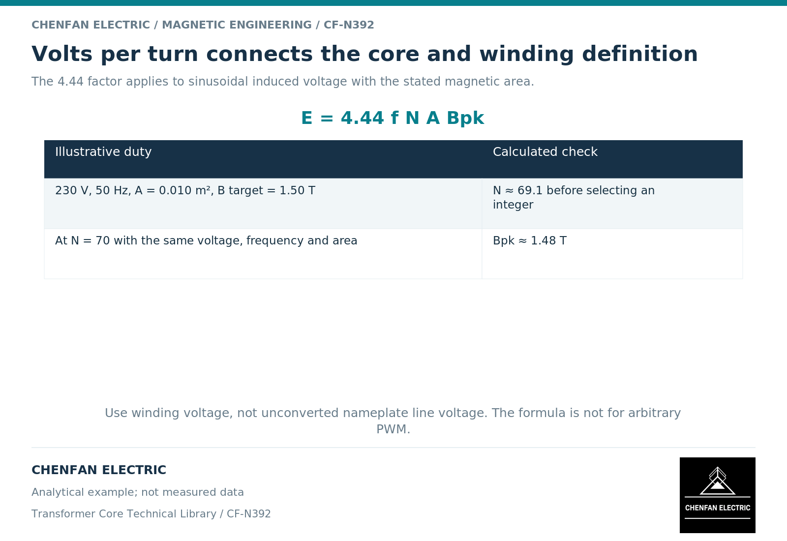
For sinusoidal induced voltage, E/N = 4.44 f A Bpk, where E is winding root-mean-square induced voltage, f frequency, A net magnetic area and Bpk peak flux density. The constant 4.44 is rounded from the sinusoidal relationship. It must not be applied unchanged to arbitrary pulse or distorted waveforms.
The area is the magnetic area represented by the design, not automatically the circle around a stepped limb or an uncorrected gross stack area.
Convert the connection before choosing turns
For a star-connected winding, phase voltage differs from line voltage by the square root of three under balanced sinusoidal conditions. For a delta-connected winding, each phase winding is connected across a line-to-line voltage. The actual winding connection and terminal definitions must be known.
Tap position can change the active number of turns or the voltage applied to the relevant winding section. Review the operating tap cases instead of checking only the nominal ratio.
Transformer design guidance also distinguishes the induced voltage from terminal behavior under winding and leakage drops. [2] For a precise operating calculation, use the intended internal voltage basis and state approximations.
Check integer turns with a transparent example
Assume, illustratively, 230 V sinusoidal induced voltage, 50 Hz, 0.010 m² net area and a chosen 1.50 T peak design target. The formula gives approximately 69.1 turns. Using 70 turns under those same assumptions gives about 1.48 T.
The example demonstrates rounding and recalculation, not a recommended operating point or a complete winding design. The selected turns must still satisfy ratio, regulation, insulation, thermal and mechanical requirements.
| Input | Common source of ambiguity |
|---|---|
| Voltage | Line, phase, terminal or induced value |
| Frequency | Nominal value versus minimum operating frequency |
| Turns | Total turns versus active turns at the selected tap |
| Area | Gross outline versus net magnetic section |
| Flux density | Peak value versus another reported convention |
| Waveform | Sinusoidal assumption versus actual voltage integral |
Carry the operating envelope into the core handover
A single volts-per-turn number does not describe overexcitation, frequency variation or transient flux offset. The core definition should identify the normal and exceptional cases that the transformer designer requires the magnetic structure to accommodate.
For non-sinusoidal voltage, calculate the relevant flux excursion from the waveform integral and account for the initial or periodic state. Equal root-mean-square voltage does not guarantee equal peak flux excursion.
The manufacturing drawing then implements the selected net area and magnetic structure. It does not independently establish the complete transformer’s voltage rating. Keeping the voltage basis, turns and area together makes design changes reviewable and prevents a familiar formula from concealing a wrong connection or waveform assumption.
References
[1] Lloyd Dixon / Texas Instruments. Magnetics Design 1 – Introduction and Basic Magnetics.
[2] Lloyd Dixon / Texas Instruments. Magnetics Design 4 – Power Transformer Design.