

Core window utilization is an allocation problem, not a contest to fit the greatest possible amount of bare conductor into an opening. Winding insulation, clearances, cooling passages, supports and manufacturing tolerances occupy part of that window. A geometrically dense arrangement can still be electrically or thermally unsuitable.
Define the numerator and denominator
A utilization factor is meaningful only when its area definitions are stated. Bare conductor metal area, insulated conductor area, winding-envelope area and total core-window area describe different quantities. Comparing factors based on different definitions can make identical designs appear different.
Transformer design guidance explicitly treats window allocation, insulation and winding arrangement as coupled decisions. [1] Its particular construction examples are not universal fill-factor recommendations for distribution or power transformers.
For a multiwinding assembly, identify which conductor sections lie in each window and how their occupancy is counted. Do not multiply a per-limb conductor total into a shared window without checking the physical arrangement.
Reserve space for functions that do not carry load current
Electrical insulation separates turns, layers, windings and grounded structures according to the design. Cooling passages provide heat-removal paths. End clearances and supports serve additional dielectric or mechanical functions. These regions cannot be treated as unused space merely because they contain no conductor metal.
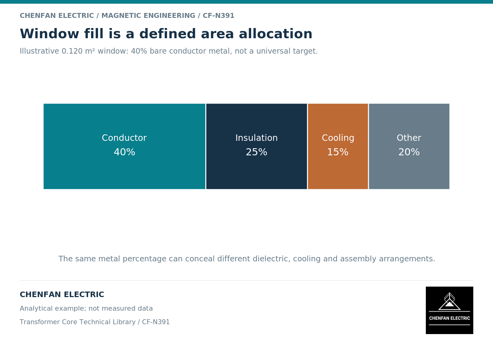
As an illustrative area budget, a 0.120 m² window allocated as 0.048 m² conductor metal, 0.030 m² insulation and clearances, 0.018 m² cooling passages, and 0.024 m² supports and remaining allowances has a bare-metal utilization of 40%. The allocation is hypothetical and not a recommended factor.
A different design can have the same 40% bare-metal utilization and a very different dielectric or thermal margin. The spatial arrangement matters as well as the area totals.
Reconcile electrical and thermal design changes
| Proposed change | Coupled effect to examine |
|---|---|
| Larger conductor section | Lower resistance may require more window space |
| More turns | Changes voltage per turn and total winding occupancy |
| Wider cooling passage | Removes conductor space but may improve heat transfer |
| Increased insulation separation | Changes fit and leakage-field geometry |
| Larger core section | Can change window size and winding mean turn length |
The voltage-per-turn relationship links core area, turns and magnetic excursion. [2] Changing turns to solve a window problem can therefore change core excitation unless other quantities are adjusted consistently.
Likewise, changing radial winding spacing can alter leakage impedance and structural field exposure. A window redesign is not complete when only the new winding envelope fits the drawing.
Release an allocation drawing, not a universal factor
The useful output is a window-section allocation showing conductor envelopes, insulation regions, cooling paths and structural allowances, tied to the winding and core revisions. Keep the definition of each reported utilization factor beside its value.
Dimensional tolerances should be assessed at the interfaces that control assembly, not added as one unexplained reserve. The design authority should identify which variations can accumulate and where the fit must be preserved.
For core manufacturing, the released window dimensions and tolerances are controlling requirements. The core supplier should not independently reduce the window on the assumption that a generic fill factor leaves spare space. The transformer designer owns the electrical and thermal allocation that makes those dimensions necessary.
A well-defined utilization factor is a useful summary of a completed allocation. It is not a replacement for that allocation, and a higher number is not automatically evidence of a better transformer design.
References
[1] Lloyd Dixon / Texas Instruments. Magnetics Design 4 – Power Transformer Design.
[2] Lloyd Dixon / Texas Instruments. Magnetics Design 1 – Introduction and Basic Magnetics.