

A gapped reactor core and a transformer core can use related magnetic materials while serving different energy duties. A reactor is commonly designed to provide a specified inductance and accommodate stored magnetic energy. A conventional transformer seeks effective mutual coupling while limiting excitation demand and loss. Matching their outer dimensions does not make the cores interchangeable.
Begin with the circuit function
For an ideal linear inductor, stored magnetic energy is W = ½LI², where L is inductance and I is instantaneous current. The expression assumes a linear, reversible relationship. For nonlinear or hysteretic behavior, energy must be evaluated from the appropriate flux-linkage relationship rather than by inserting an arbitrary inductance into the same formula. [1]
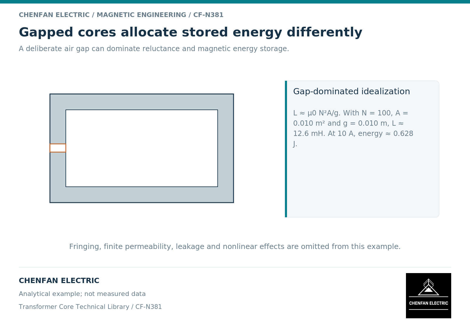
An air gap increases reluctance and permits a larger magnetomotive force at a given core flux density. In a high-permeability gapped structure, much of the magnetic energy can be stored in the gap and its surrounding field. Inductor design guidance explains this distinction from a low-excitation transformer magnetic path. [2]
For a fixed-geometry, reversible nonlinear relation, stored energy is the integral of i d(lambda), while coenergy is the integral of lambda di, from a stated zero-energy reference. They are equal for the linear case, not generally for the nonlinear case. With hysteresis, a closed-cycle integral also includes dissipation, so a single curve does not define recoverable energy for every history. [3]
A transformer still has stored field energy, including leakage and magnetizing contributions. The distinction is the design objective, not an assertion that transformers store none.
See what the gap changes in a simple model
For a uniform gap of length g and area A, neglecting fringing, gap reluctance is approximately g/(μ₀A). If that gap dominates the total reluctance, L is approximately μ₀N²A/g, where N is turns and μ₀ is the permeability of free space.
As an illustrative calculation, N = 100, A = 0.010 m² and g = 0.010 m give L ≈ 0.0126 H. At 10 A, the corresponding ideal linear stored energy is about 0.628 J. These are analytical example values, not a reactor design or a measured result.
The calculation excludes core reluctance, fringing, leakage, nonlinear material response and winding effects. It is useful for checking dependencies: more turns increase inductance strongly, while a longer dominant gap reduces it. It is not sufficient for manufacturing release.
Specify the current and voltage envelope together
| Requirement | Why it changes the magnetic task |
|---|---|
| Inductance definition | Small-signal, incremental and large-signal values can differ |
| Peak and continuous current | Establishes magnetic excursion and winding duty |
| Direct-current bias and ripple | Defines the operating point and cyclic excursion |
| Frequency spectrum | Affects loss, impedance and fringing-related heating |
| Voltage waveform | Determines flux-linkage change and insulation duty |
| Thermal and mechanical limits | Constrains the complete reactor assembly |
A low-current inductance reading does not establish behavior at the required current. A material loss value at one alternating flux condition does not establish performance under bias and ripple.
Treat substitution as a redesign question
Adding a gap to a transformer core changes more than its nominal inductance. It can create concentrated fringing fields, alter local losses and forces, and require different winding placement or support arrangements. Inductor guidance explicitly identifies the field near a discrete gap as a separate design concern. [2]
The comparison should therefore include magnetic energy, inductance over the operating range, local field exposure, winding loss, temperature and mechanical integration. The core drawing is only one part of that evidence.
For a core enquiry, identify whether the requested object belongs to a transformer or a reactor duty before discussing material equivalence. Educational coverage of reactor cores does not establish that a supplier has a qualified complete-reactor product. The responsible designer must release the magnetic and assembly requirements for the actual application.
References
[1] Lloyd Dixon / Texas Instruments. Magnetics Design 1 – Introduction and Basic Magnetics.
[2] Lloyd Dixon / Texas Instruments. Magnetics Design 5 – Inductor and Flyback Transformer Design.
[3] David Meeker. Finite Element Method Magnetics User Manual.