

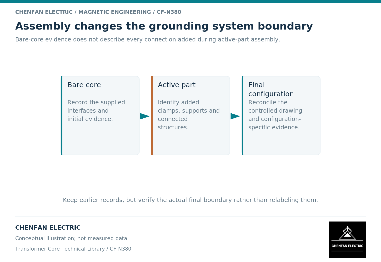
Core grounding should be reviewed again after active-part assembly because the electrical system has changed. Windings, clamps, lead supports, shields and restraints can add coupling or conductive paths that were absent during a bare-core inspection. A valid earlier result remains useful, but it does not automatically describe the integrated assembly.
Preserve the earlier evidence without extending its scope
A bare-core report should retain its identity, drawing revision, test object and configuration. Do not relabel it as a final active-part result simply because the same core serial number appears in both records.
Core-grounding research relates current and potential behavior to the network of windings, core and other structures. [1] Adding those structures changes the physical boundary that a later review must consider.
This does not mean every earlier test is invalid or must be repeated indiscriminately. The responsible process should identify which conclusions remain applicable and which interfaces require new evidence after integration.
Trace what assembly adds
Create a difference record between the bare-core state and the integrated state. Focus on components that touch, support, surround or connect to the core and its grounding system.
| Added or revised item | Boundary question |
|---|---|
| Winding insulation and supports | Has the intended core separation been preserved? |
| Clamps and structural restraints | Have conductive routes changed? |
| Lead-support hardware | Are metal inserts and contacts represented? |
| Shields and screens | Is each electrical potential deliberately defined? |
| Monitoring interfaces | Does the installed topology match the drawing? |
| Temporary assembly items | Are they included in, or excluded from, the final state? |
This is a review inventory, not an instruction for handling or removing components.
Reconcile the mechanical and electrical records
A final mechanical drawing can be correct while its electrical relationship to the core is undocumented. Conversely, a schematic can show the intended isolation without proving that the assembled interfaces maintain it. Use both records together.
Electrical testing has distinct purposes and object definitions; it should be selected and documented accordingly. [2] A report must identify the assembly stage, node pair, approved configuration and applicable criterion rather than simply record that “grounding was checked.”
A difference in results should be investigated against the changed configuration. New capacitive coupling, an altered measurement path, an unwanted contact and an instrument change are different explanations. Retaining the earlier record helps distinguish them.
Close the system boundary at final release
The final review should state which electrical nodes exist, how their intended connections are established, which insulation boundaries remain, and where the supporting evidence is recorded. Any unresolved exception should have an assigned disposition rather than being hidden by a general pass statement.
The transformer original equipment manufacturer owns the complete active-part grounding design and final integration. The core supplier owns the agreed features and evidence within its delivered scope. These responsibilities can be coordinated without treating them as interchangeable.
No test voltage or connection sequence is specified here. Work on the grounding system requires the approved equipment-specific process. The practical point is documentary and technical: carry earlier evidence forward accurately, identify what assembly changed, and verify the final boundary instead of assuming that a bare-core acceptance automatically approves the whole transformer.
References
[1] Xiu Zhou and coauthors / Frontiers in Energy Research. Analytical modeling and calculation of core grounding current in converter transformer (2023).
[2] OMICRON. Common Electrical Tests on Power Transformers.