

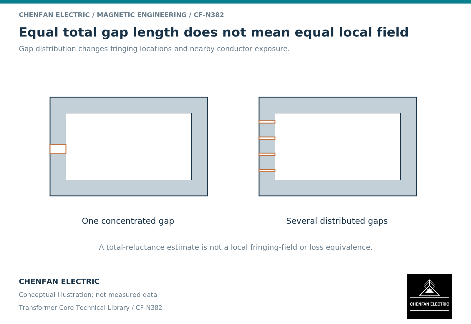
Distributed and concentrated air gaps can provide similar nominal reluctance while producing different local fields and mechanical layouts. Dividing one gap into several smaller gaps is therefore a design choice, not a universal efficiency upgrade. The comparison must retain the same inductance definition, current duty, material and winding arrangement.
Separate total reluctance from local geometry
In a simplified linear magnetic path with equal cross-sectional area and negligible fringing, gap reluctances in series add. Under those assumptions, several gaps whose lengths sum to g have the same total gap reluctance as one gap of length g. [1]
This is a useful limiting-case check, not a complete equivalence. Each real gap has edge fields, neighboring material and a position relative to the winding. Inductor design guidance identifies fringing and winding placement as factors that change the external field and effective inductance. [2]
Distributed gaps may mean several discrete gaps in a segmented structure or microscopic distributed nonmagnetic regions in another material system. These constructions should not be treated as interchangeable simply because both use the word “distributed.”
Compare field exposure where conductors actually sit
One concentrated gap can create a strong local fringing region. Several smaller gaps can redistribute that exposure, but the outcome depends on their locations and surrounding conductors. A winding or clamp placed close to several gap edges may still experience significant additional loss.
The comparison should show where the field intersects winding turns, supports and other conducting parts. Reporting only average core flux density misses the effect that motivated the gap redesign.
A fair study also retains the same total ampere-turns and operating waveform. If one candidate uses a different current or a different number of turns, its lower field cannot be attributed solely to gap distribution.
Account for construction and tolerance accumulation
| Comparison item | Concentrated-gap question | Distributed-gap question |
|---|---|---|
| Reluctance | How sensitive is the main gap? | How do individual gaps combine? |
| Fringing exposure | Which nearby parts see the local field? | Where is exposure redistributed? |
| Mechanical support | How is the gap maintained? | How are multiple interfaces restrained? |
| Manufacturing variation | Which dimensions dominate? | Are variations correlated or independent? |
| Verification | What operating-point inductance is checked? | Is the same definition used? |
For a dominant-gap approximation, a small relative increase in total gap length produces an approximately equal relative decrease in inductance. That sensitivity follows from L being proportional to 1/g; it does not quantify actual production variation without dimensional and material evidence.
Multiple interfaces can introduce additional assembly and verification work. Those costs may be justified, but they should appear in the comparison rather than being concealed behind a magnetic advantage.
Choose against the complete duty
Evaluate inductance over current, total loss, local temperature, acoustic or mechanical response where relevant, and the practical assembly constraints. A solution favorable at small ripple may rank differently under a larger alternating excursion or a changed conductor layout.
The final drawing should define the gap arrangement and its tolerances as part of the released magnetic design. Do not substitute a different arrangement on the basis of total gap length alone.
The useful decision is whether the chosen distribution meets the actual electromagnetic and mechanical requirements more effectively. It is not whether one construction sounds more advanced. Both concentrated and distributed arrangements can be appropriate within a verified design envelope.
References
[1] Lloyd Dixon / Texas Instruments. Magnetics Design 1 – Introduction and Basic Magnetics.
[2] Lloyd Dixon / Texas Instruments. Magnetics Design 5 – Inductor and Flyback Transformer Design.