

Core ground-lead monitoring records current in a particular conductive path. It can reveal a change worth investigating, but it does not independently identify the cause, the location of an unwanted connection or the temperature of a hidden component. Interpretation begins with a known grounding topology and a credible operating baseline.
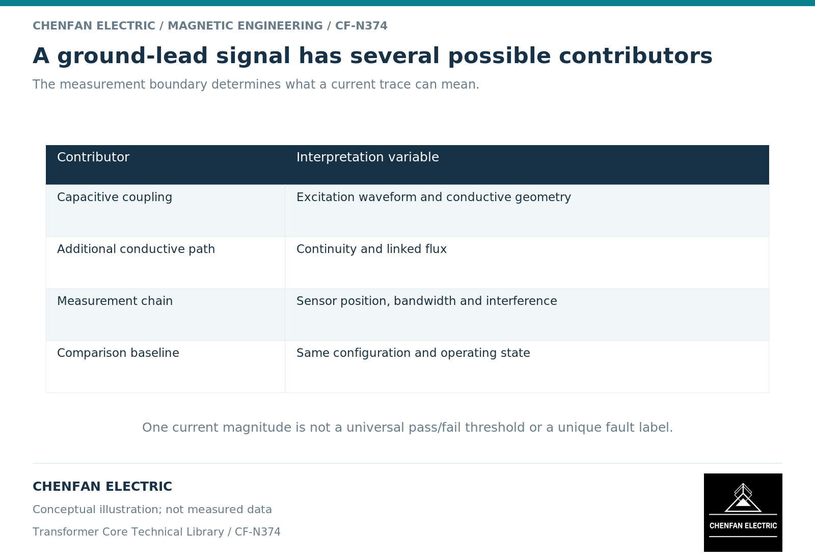
Recognize more than one contribution
Capacitive coupling between windings, the core and other structures can contribute to ground current. A converter-transformer study explicitly models these couplings and their dependence on the electrical configuration. [1] A changing magnetic field linked by an unintended conductive loop can provide a different contribution. [2]
For an ideal capacitor, instantaneous current is C times the rate of change of voltage. This relation explains why waveform and frequency matter, not only voltage magnitude. Real assemblies contain distributed capacitances and additional paths, so one lumped capacitor is only a conceptual illustration.
A monitor may also be affected by nearby fields, bandwidth limits, range selection and signal-processing choices. Distinguish a physical change from a changed measurement system before interpreting a trend as deterioration.
Build a baseline with operating context
A baseline should identify the monitored lead, sensor orientation and location, instrument configuration, grounding drawing revision and assembly state. Record voltage, load, tap, relevant waveform information and cooling or operating transitions where they affect interpretation.
A root-mean-square value summarizes magnitude but does not preserve frequency content or phase relationships. Two signals can have the same root-mean-square value and different physical origins. Retain waveform or spectral information when it is part of the diagnostic method.
Trend comparisons are strongest when the measurement definition is unchanged. A replacement sensor with a different bandwidth can change the reported current without any change in the transformer.
Interpret patterns as hypotheses
| Pattern | Useful next comparison |
|---|---|
| Step change after maintenance | Assembly and grounding configuration before and after |
| Variation with voltage | Capacitive coupling and excitation-related mechanisms |
| Variation with load | Leakage-field exposure and current-path hypotheses |
| New harmonic content | Supply waveform, sensor response and nonlinear effects |
| Intermittent excursions | Operating events, connection condition and interference |
None of these patterns alone proves a fault. They narrow the questions and help select the appropriate authorized inspection or test.
A sensor on one designated lead may not observe an entire circulating loop or all parallel paths. Therefore, a small reading is not a blanket certificate of correct grounding, and a large reading is not a direct estimate of internal heating.
Use equipment-specific decision rules
Alarm and action criteria belong to the responsible manufacturer’s design, the monitoring system and the owner’s approved maintenance strategy. They should reflect the equipment configuration and evidence, not a current threshold copied from a different research example.
The report should separate the observation, its uncertainty, the proposed mechanism and the required confirmation. Preserve the original signal and operating record when an investigation begins. Do not overwrite the baseline with a new “normal” simply because the reading has changed.
Monitoring is valuable when it creates a traceable early question. It becomes misleading when a number is treated as a complete diagnosis or used to justify disconnecting a ground lead without an approved safety and testing process.
References
[1] Xiu Zhou and coauthors / Frontiers in Energy Research. Analytical modeling and calculation of core grounding current in converter transformer (2023).
[2] Lloyd Dixon / Texas Instruments. Magnetics Design 1 – Introduction and Basic Magnetics.