

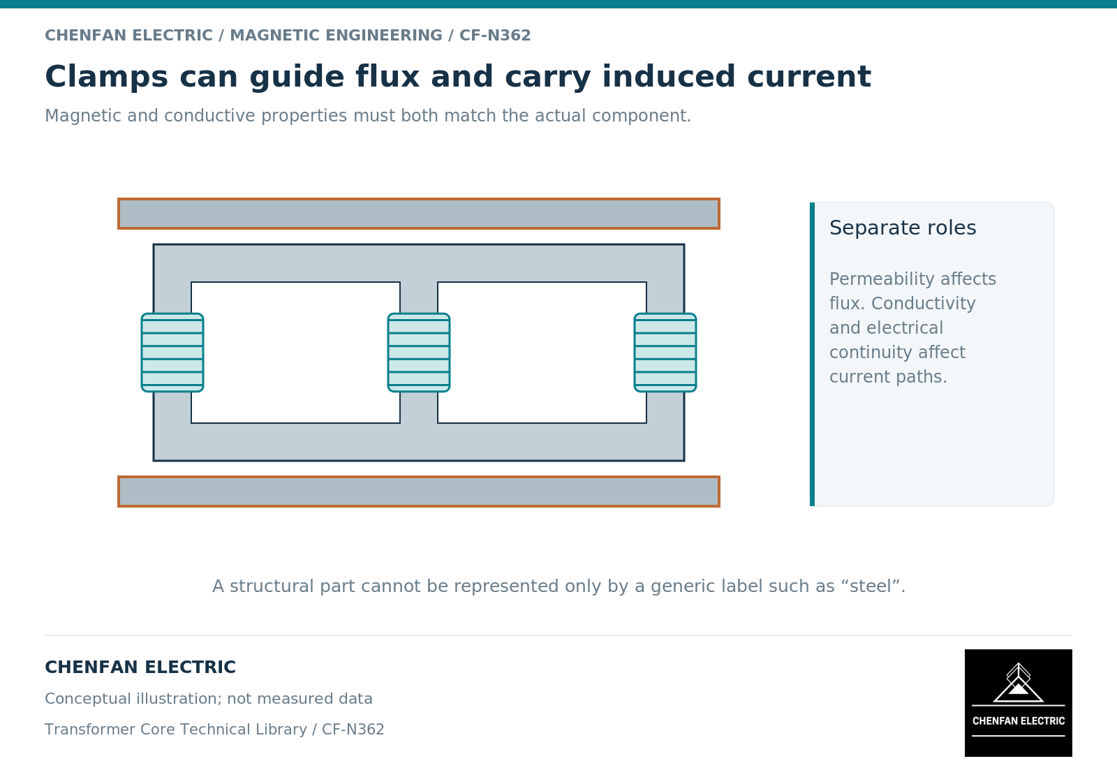
A transformer clamp can participate in two different networks: a magnetic path that redirects flux and an electrical path that carries induced current. Its permeability influences the first; its conductivity and electrical connections influence the second. Treating “steel clamp” as a sufficient material definition can therefore produce the wrong field distribution and the wrong heating estimate.
Separate magnetic attraction from electrical circulation
Permeability relates magnetic field strength to flux density, with nonlinear and directional behavior where relevant. Conductivity relates electric field to current density. A conductive component need not be strongly magnetic, and a highly permeable component is not automatically immune to eddy-current heating. These properties enter electromagnetic models separately. [1]
The distinction matters at an assembly interface. Two clamp pieces may form a magnetic return across a small intervening region while remaining electrically insulated. Alternatively, a connection through bolts, supports or adjoining metalwork may complete an electrical loop that a simplified clamp drawing omits.
Do not substitute mechanical contact for an electrical boundary condition. The design must identify intended conductive connections and insulating interfaces; their condition and verification belong to the controlled assembly definition.
Trace the source field before changing the clamp material
Load-related fields arise from winding and lead current distributions. A clamp near a winding end can experience a different field orientation from one beside a limb, even when both are made from the same stock. Transformer field treatments distinguish winding leakage effects from the main mutual flux. [2]
A material comparison that holds only core flux density constant is therefore incomplete. Hold winding geometry, current waveform, phase relations, lead routing and surrounding structures constant as well. Otherwise a lower predicted clamp loss may reflect a changed source rather than an improved clamp.
The return path deserves equal attention. Moving flux away from one component can increase exposure elsewhere. Review the adjacent tank, support connections and shield ends rather than reporting only the selected clamp’s reduction.
Build the minimum useful property record
| Model input | Why a generic description is insufficient |
|---|---|
| Magnetic constitutive data | Permeability may change with field level and direction |
| Electrical conductivity | Induced-current distribution depends on conduction |
| Actual thickness and shape | Penetration, edge crowding and loop area change |
| Connection and insulation map | Separate parts may become one conducting network |
| Frequency spectrum | Fundamental and harmonic fields need appropriate treatment |
| Thermal interfaces | Equal loss does not imply equal temperature |
Material provenance should distinguish measured data, supplier data and assumed screening values. A preliminary conductivity value can support a sensitivity study, but it should not silently become a released design property.
Judge changes by a coupled outcome
Consider a proposed clamp redesign that reduces magnetic permeability. It may redirect flux, but it can still support induced currents if the conductive path remains. Conversely, interrupting one electrical route in a model changes the current distribution but does not establish that the real component can be altered safely or mechanically.
The appropriate design result combines field redistribution, dissipated power, local temperature and mechanical function. It should retain uncertainty around contacts and material response where these inputs are not established.
For procurement, request the defined clamp material and interface drawing rather than a promise of “non-heating steel.” For engineering review, require the modeled electrical network alongside the magnetic result. Neither task is resolved by changing clamping pressure or by replacing the core grade without demonstrating the relevant mechanism.
References
[1] David Meeker. Finite Element Method Magnetics User Manual.
[2] Lloyd Dixon / Texas Instruments. Magnetics Design 4 – Power Transformer Design.