

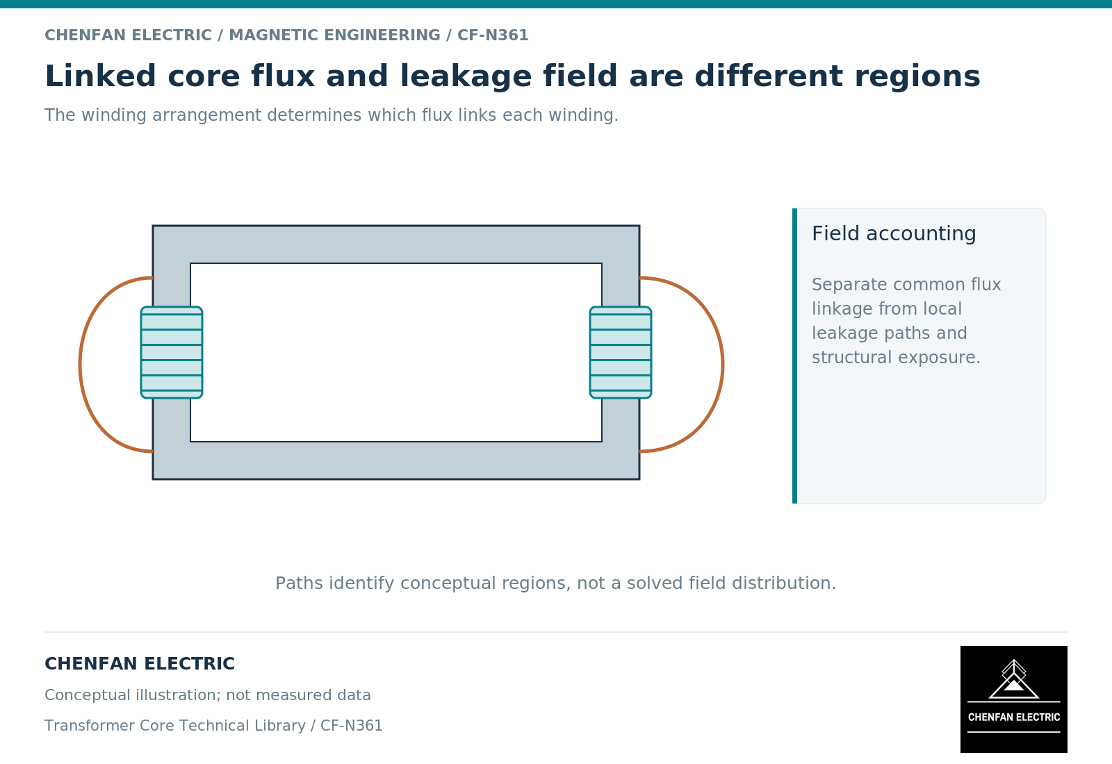
Core flux and leakage flux are distinguished by winding linkage, not simply by whether a field is drawn inside or outside a steel outline. The useful engineering distinction is between the flux that provides the intended mutual coupling and the field contributions that do not link all relevant turns equally. That distinction prevents a structural hot spot from being misclassified automatically as a core-material problem.
Start with the winding pair and operating condition
In a two-winding representation, mutual flux links both windings, whereas leakage components account for incomplete linkage. Transformer design treatments separate these contributions because they play different roles in induced voltage, impedance and stored field energy. [1]
The division is a modeling convention tied to the windings being considered. A field may link one secondary but not another in a multiwinding transformer. Calling it simply “the leakage flux” without identifying the winding pair can conceal that distinction.
Main flux is governed principally by the induced winding voltage integral and turns. Load-related fields depend on the locations and balance of winding ampere-turns. Terminal voltage, internal voltage drops and load condition must still be reconciled; the separation is not a claim that the two systems never interact.
Map the region to the question
A core model needs the limbs, yokes, joints and relevant return paths. A leakage-field study may need winding ends, leads, clamps, shields and the tank. The same assembly can therefore require different spatial detail for different decisions.
| Observed concern | First field description to examine |
|---|---|
| Increased excitation at unchanged frequency | Main-flux operating point and magnetic state |
| Changed short-circuit impedance | Winding-pair leakage linkage and geometry |
| Local clamp heating under load | Structural exposure and conductive current paths |
| Lead-adjacent tank heating | Lead and return-current geometry |
| Unexpected vibration | Force distribution and structural response |
These are investigation routes, not diagnoses. More than one mechanism can contribute to an observation.
Do not infer a loss allocation from a color plot
A high local flux density is not itself a loss in watts. Electromagnetic losses require the appropriate constitutive model, excitation spectrum and conducting geometry. Temperature adds heat-transfer conditions and duration.
Finite-element formulations distinguish magnetic response from conductivity and induced-current behavior. [2] Assigning the core-steel loss curve to a solid clamp or tank wall skips that distinction. Likewise, a leakage-inductance value cannot identify where the associated structural loss is dissipated.
For a useful comparison, retain the same current definition, winding connection, reference side and geometric revision. If one study uses rated sinusoidal current and another a distorted partial-load waveform, label the difference before comparing results.
Use a two-boundary review
First review the magnetic boundary: which windings link the modeled flux, and which branches or regions carry its return? Then review the evidence boundary: is the reported quantity material loss, assembled-core loss, winding loss, structural loss or complete-transformer loss?
A simple drawing can support this review without pretending to be a simulation. Mark the main mutual path, the winding-end region and the structural parts included in the study. Identify omitted lead routes and any assumed symmetry. This exposes missing scope more effectively than a visually elaborate but undocumented field image.
For the core supplier, the actionable output is the controlled core geometry and magnetic operating envelope. For the transformer designer, it is the additional field and thermal assessment needed around that core. Maintaining both responsibilities avoids asking a material certificate to answer an assembly-level question it never measured.
References
[1] Lloyd Dixon / Texas Instruments. Magnetics Design 4 – Power Transformer Design.
[2] David Meeker. Finite Element Method Magnetics User Manual.