

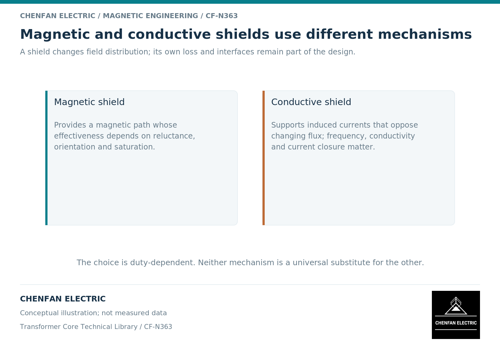
Magnetic and conductive shields reduce exposure through different mechanisms. A magnetic shield provides a favorable magnetic path; a conductive shield develops induced currents that oppose changes in the linked field. Both can redistribute the field and generate heat. Neither should be evaluated as a passive wall that simply makes flux disappear.
Identify the dominant mechanism
A high-permeability path can guide flux away from a protected region, subject to its geometry, local saturation and material direction. A conductive shield acts through electromagnetic induction; its response depends on frequency, conductivity, thickness and current continuity. Finite-element magnetic formulations treat these inputs independently. [1]
A practical shield may exhibit both mechanisms. Naming a component “magnetic shielding” does not remove its electrical conductivity from the model, and naming it “conductive shielding” does not establish that its permeability is negligible.
At a steady direct-current field, a normal conductor does not sustain the same eddy-current shielding mechanism that it develops during field changes. A static-field calculation and an alternating-field calculation therefore answer different questions. Specify the operating spectrum rather than assigning one universal shielding factor.
Protect a defined region, not an abstract field value
Define the protected quantity: tank-wall loss, clamp temperature, local field near a lead, or exposure at another identified region. Then define the source current and its return geometry.
Transformer leakage-field behavior depends on winding arrangement and linkage. [2] A shield assessed against an isolated source may behave differently after neighboring phases, return conductors and structural connections are included.
An attractive result at one point can conceal a larger field at a shield edge. Evaluate the relevant volume and adjacent structures, not only the point selected for a presentation. Compare the same spatial metric between designs: a point peak, an area average and integrated loss are not interchangeable.
Compare candidate shields on an explicit basis
| Review item | Magnetic-path emphasis | Conductive-response emphasis |
|---|---|---|
| Constitutive input | Directional, nonlinear magnetic response | Conductivity and frequency response |
| Geometry | Flux path, joints and local cross-section | Thickness, edges and current continuity |
| Important limitation | Local saturation and redistribution | Resistive heating and incomplete shielding |
| Shared requirement | Thermal and mechanical integration | Thermal and mechanical integration |
The comparison should also state installation tolerances, support details and electrical potential control. These are part of the design, not optional accessories added after an electromagnetic calculation.
Close the thermal and assembly questions
A shield may reduce loss in the protected tank region while dissipating power in itself. That can be an acceptable design outcome only when the shield’s temperature, insulation interfaces and cooling path have been assessed. A percentage reduction without the starting loss and redistributed heat is not enough.
For a conceptual screening study, show separate results for the shield and the protected structure. Mark the assumptions about connections and material data. For a design release, retain the approved configuration and the evidence supporting its operating envelope.
This is not a recommendation to add shielding to an existing transformer or alter conductive paths in service. The useful conclusion is a comparison method: identify the mechanism, hold the source condition constant, account for displaced losses, and verify the installed assembly. A material label alone cannot settle those four questions.
References
[1] David Meeker. Finite Element Method Magnetics User Manual.
[2] Lloyd Dixon / Texas Instruments. Magnetics Design 4 – Power Transformer Design.