

A magnetic equivalent circuit is useful when the engineering question can be answered through branch fluxes, magnetomotive forces and coupled winding behavior without resolving every local field detail. Its strength is an explicit physical simplification. Its weakness appears when a lumped branch is asked to predict a spatial hot spot that it does not contain.
Translate geometry into a network deliberately
In a simple uniform linear branch, reluctance is length divided by permeability and area. Magnetomotive force is related to winding ampere-turns, and branch fluxes satisfy continuity at junctions. These relations support a network analogy, but reluctance is not an electrical resistor dissipating heat. [1]
The branch layout should follow the relevant limbs, yokes, gaps and return regions. Combining several physical regions into one element is acceptable only when their separate behavior is not needed for the decision.
For a nonlinear core, branch reluctance changes with the operating point. With hysteresis, the state history can also matter. A fixed network topology can remain useful while its constitutive branches become nonlinear or history dependent.
Preserve the winding-to-core mapping
Each winding must link the correct branch or combination of branches, with consistent turns and polarity. A geometrically plausible reluctance network can still produce an incorrect electrical response if the winding mapping is wrong.
The unified magnetic equivalent circuit approach illustrates how core geometry and winding coupling can be represented together. [2] It also shows why a shared three-phase core differs from three unrelated magnetizing branches.
Leakage behavior needs its own treatment. Do not assume that a main-core reluctance network automatically includes all field energy between windings or near leads. The electrical and magnetic representations must agree on which contributions are explicit and which are lumped.
Test the simplification against limiting cases
An initial check should verify magnetic continuity, winding polarity and expected symmetry under a symmetric excitation. A second check should examine a deliberately unbalanced case to see whether the represented return paths behave consistently.
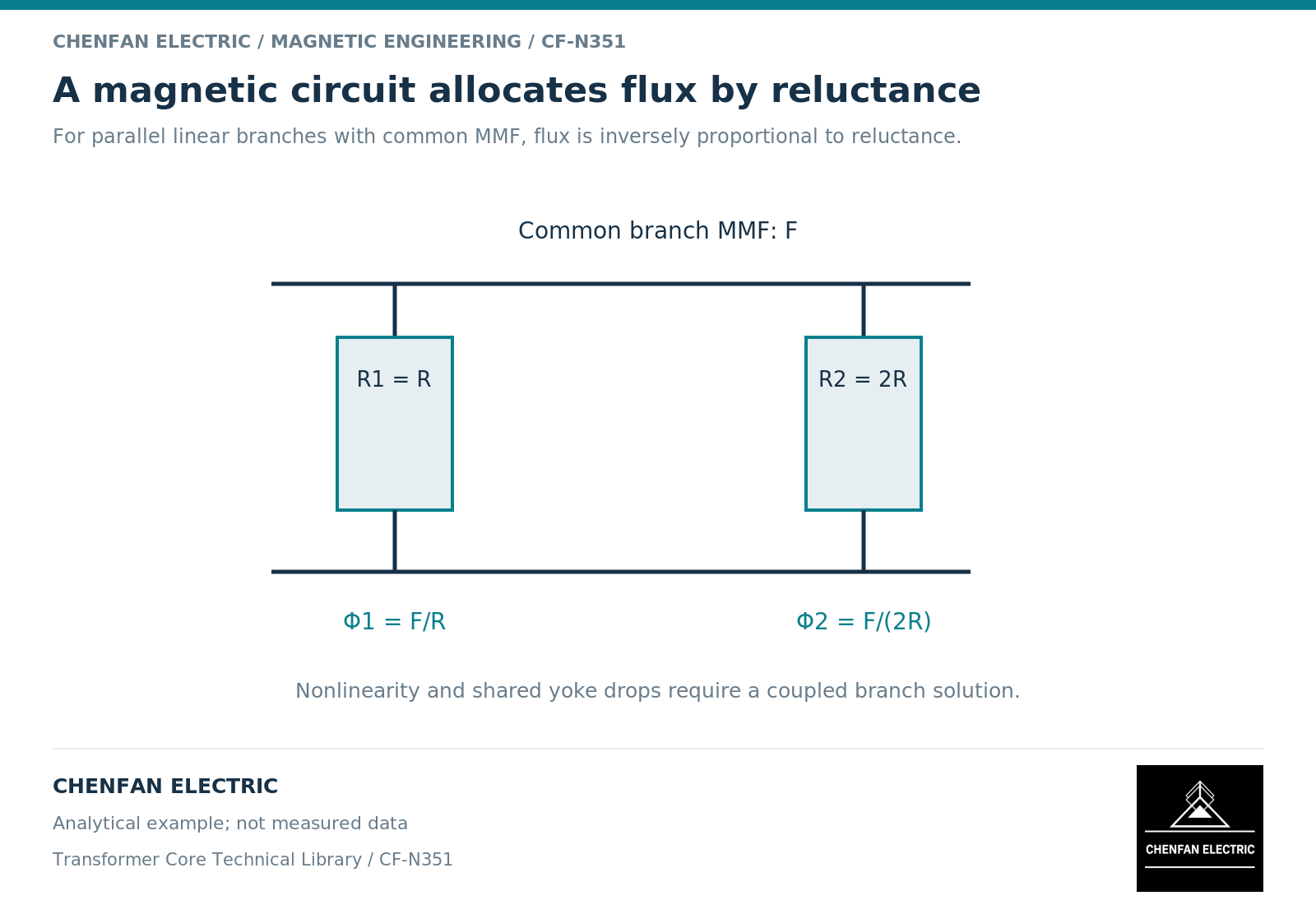
An illustrative two-return network with identical linear reluctances should divide an imposed return flux equally. If one reluctance is doubled while the other is unchanged, the lower-reluctance branch carries twice the flux of the higher-reluctance branch under the same branch magnetomotive-force drop. This is a network check, not a prediction for a nonlinear assembled core.
Such simple checks catch topology and sign errors before a complex transient obscures them. They also make the model easier to review by someone other than its author.
State where the network stops being descriptive
| Intended output | What the network must retain |
|---|---|
| Limb-average flux | Correct branch topology and area |
| Excitation current | Constitutive response and winding mapping |
| Zero-sequence behavior | Electrical connections and return branches |
| Local joint field | Additional spatial detail or a justified submodel |
| Structural hot spot | Distributed electromagnetic and thermal evidence |
A calibrated branch can reproduce a terminal response while combining several omitted mechanisms. Its fitted value should not then be interpreted as a measured property of one physical component.
The final model note should list the represented regions, parameter origins, calibration cases and unsupported outputs. For core procurement, it should point to the geometry revision and branch-flux requirements passed to the manufacturer. The benefit is a transparent model that answers a defined question, not the appearance of completeness created by drawing more circuit elements.
References
[1] Lloyd Dixon / Texas Instruments. Magnetics Design 1 – Introduction and Basic Magnetics.
[2] Manitoba Hydro International / PSCAD. The UMEC Approach.