

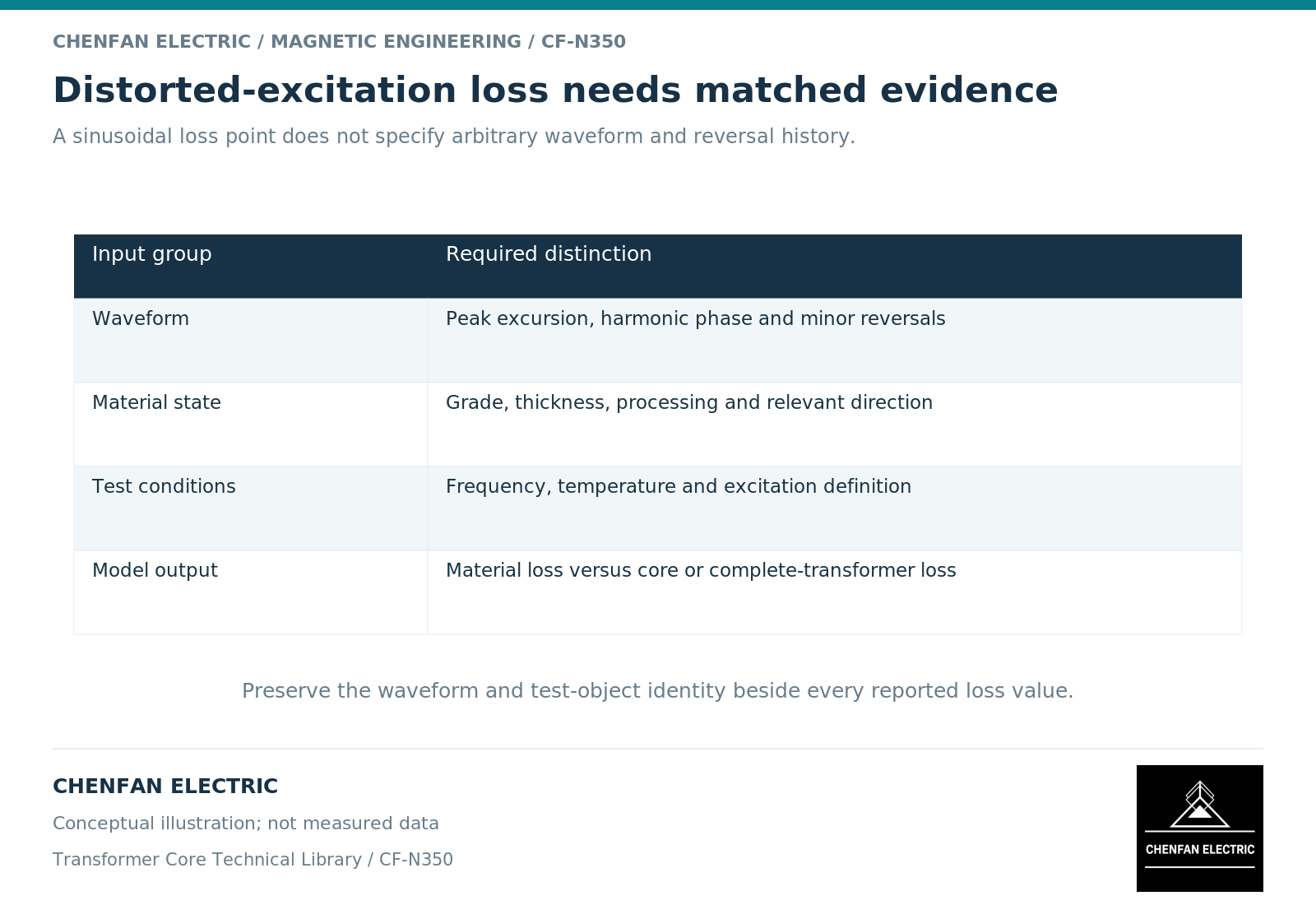
Predicting core loss under distorted excitation requires the actual flux trajectory and material data that support the chosen loss model. A sinusoidal loss value at the same root-mean-square voltage is not a complete substitute. Distortion changes the time history, possible reversals and rate-dependent response.
Reconstruct the magnetic excitation first
Begin with the induced winding-voltage waveform, turns, tap and net-area basis. Integrating the voltage establishes the change in linked flux. [1] Preserve harmonic phase information or the original time record when waveform extrema and reversals matter.
Do not infer core excitation from load-current distortion alone. The winding circuit and applied voltage determine how current harmonics relate to the magnetic field. Voltage and current spectra serve different parts of the transformer-loss assessment.
For a shared core, local branch trajectories can differ from a single average waveform. A whole-core calculation may need to distinguish limbs, yokes and joint regions rather than apply one density everywhere.
Identify the loss model’s evidence range
A model may use measured waveform-specific loss data, an empirical expression or an explicit hysteretic and eddy-current formulation. Each has a calibration boundary. State the material, temperature, density range, frequency range and waveform families used to support it.
A normal B-H curve does not contain every dissipative mechanism. Effective frequency-domain magnetic models also have a different purpose from full time-domain history models. [2] A converged field solution is therefore not sufficient evidence that the associated loss prediction is valid.
Where a fitted formula is used, retain its coefficients, units and source dataset. Avoid combining coefficients from one material or temperature with a different operating waveform merely because the equation is available in a spreadsheet.
Keep material, assembly and transformer losses distinct
Material-specific loss is usually expressed per unit mass or volume under defined excitation. An assembled-core result includes the geometry and manufacturing boundary. A complete-transformer no-load measurement includes additional contributions associated with the assembled electrical system.
A distorted-excitation model should state which of these it predicts. A material calculation multiplied by total core mass is not automatically a validated assembled-core result, and neither is a prediction of winding or tank loss.
| Evidence layer | What it contributes |
|---|---|
| Waveform record | Time-domain excitation boundary |
| Material dataset | Constitutive and loss behavior under defined conditions |
| Core geometry | Spatial distribution and mass allocation |
| Assembly validation | Check of the combined magnetic model |
| Thermal assessment | Consequence of the predicted loss distribution |
A single building factor cannot be assumed to remain constant across every distorted waveform unless relevant evidence supports that use. Also identify which loss mechanisms are already included in each material dataset or solver output. A measured total dynamic loss must not have the same eddy-current contribution added again as a separate correction. Solver output definitions distinguish individual mechanisms from total loss. [3]
Validate a different waveform, not only another amplitude
A useful validation set includes a waveform not used to fit the model, especially when minor reversals or bias are central to the intended application. Compare the loss quantity with its measurement uncertainty and retain the voltage and current records used to derive it.
Also inspect sensitivity to phase angles, baseline treatment and uncertain material parameters. If these uncertainties materially change the decision, report a range rather than a precise watt value.
The final technical statement should identify the predicted loss boundary, evaluated waveforms and validation evidence. It should not claim a universal percentage increase caused by distortion. For core procurement, the outcome is a defined magnetic duty and verification basis, not a request to guarantee performance from a sinusoidal steel certificate alone.
References
[1] Lloyd Dixon / Texas Instruments. Magnetics Design 1 – Introduction and Basic Magnetics.
[2] Nirmal Paudel / COMSOL. Model Magnetic Materials in the Frequency Domain with an App (2016).
[3] David Meeker. Finite Element Method Magnetics User Manual.