

Voltage-waveform measurements used to validate a magnetic model need more than a plotted trace. The record must preserve channel scaling, timing, bandwidth, reference connection and baseline treatment. Errors that look small in voltage can become significant after integration into flux.
Define the measurement quantity and model quantity
The instrument records a terminal-related voltage under a particular connection. The model may require induced winding voltage, mutual flux linkage or a local magnetic quantity. State the transformation between them.
The voltage-flux relation gives a change in linked flux from the induced-voltage integral. [1] It does not automatically convert every terminal channel into local density. Turn count, tap position, circuit drops and magnetic area are additional inputs.
For three-phase work, retain phase identification and synchronized timing. A channel delay or polarity inversion can distort the reconstructed interphase relationship even when each individual trace looks reasonable.
Match acquisition to the waveform features that matter
Bandwidth and sampling must support the components used by the model, with appropriate treatment of aliasing and instrument response. A record adequate for fundamental amplitude may be inadequate for switching edges or a small high-frequency component.
Conversely, excessive emphasis on fast edges can distract from a low-frequency baseline error that dominates the flux integral. The acquisition and processing plan should be driven by the target observable: peak flux, minor reversals, harmonic current or a transient offset.
Document any filtering. A filter can change amplitude and phase, and its delay may need to be accounted for when voltage and current records are compared. Do not validate a model against a processed waveform whose transformation is unknown.
Quantify the errors that integrate
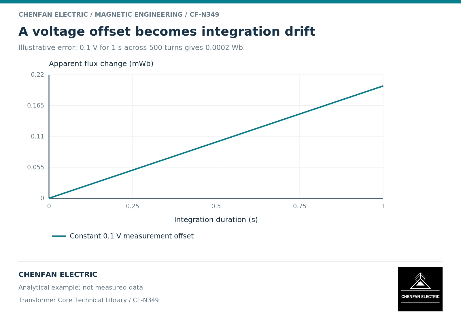
A constant offset error epsilon over a duration T creates a flux error epsilon T/N. An illustrative 0.1-volt offset over one second in a 500-turn winding gives 0.0002 weber. The corresponding density error depends on the relevant net area.
Scaling error affects every integrated component, while timing error affects phase relationships and the location of extrema. Missing samples or a record beginning after the event can omit genuine volt-seconds.
Circuit-model uncertainty also belongs in the error budget. Nonlinear transformer models show why leakage drops and magnetizing-branch placement can matter when reconstructing the core-driving voltage. [2]
Compare model and measurement on the same basis
| Validation item | Required alignment |
|---|---|
| Voltage channel | Same winding and polarity definition |
| Time reference | Same event origin and channel synchronization |
| Processing | Known filters, resampling and baseline treatment |
| Initial state | Measured estimate or explicit assumption |
| Comparison metric | Same peak, root-mean-square, phase or integral definition |
Use more than one metric. Agreement in root-mean-square voltage can coexist with disagreement in phase or cumulative area. A transient model may match the first peak while missing the subsequent decay.
Retain the raw record, processed record and model input separately. This makes the validation reproducible and allows later reviewers to distinguish a model error from a data-processing choice.
The final report should state the measurement uncertainty and the range of behavior actually checked. It should not present a smooth overlay as proof of complete model accuracy. A clear, traceable waveform record is often more valuable than a more elaborate magnetic model supplied with poorly defined excitation data.
References
[1] Lloyd Dixon / Texas Instruments. Magnetics Design 1 – Introduction and Basic Magnetics.
[2] Manitoba Hydro International / PSCAD. The Classical Approach.