

Flux walking is a progressive displacement of a transformer’s flux trajectory caused by an imbalance in the effective volt-seconds applied over successive cycles. It is a circuit-and-excitation problem, not a synonym for every asymmetric current waveform. Identify the converter topology and the actual induced-voltage balance before using the term.
Track the cycle-to-cycle integral
For a winding with N turns, the change between equivalent cycle boundaries is integral(e dt)/N over that cycle. [1] A nonzero result changes the starting flux for the next cycle in the ideal integration picture.
Unequal pulse durations, unequal effective voltage levels or an incomplete reset process can create such an imbalance in a switched circuit. The relevant voltage is the voltage that drives mutual flux, after accounting for circuit drops when they matter.
An initially offset but subsequently balanced trajectory is different. It may reflect residual flux and closing conditions rather than continuing cycle-to-cycle walking.
The real circuit does not permit unlimited ideal drift
As current becomes asymmetric, winding and switch voltage drops can change the effective volt-seconds. Control action may also intervene. The nonlinear magnetizing response couples the evolving flux back into the circuit.
Transformer-design guidance discusses this interaction in switched-power circuits. [2] Its mechanism is useful, but a small-converter example should not be converted into an operating rule for a utility transformer connected through a different filter and control system.
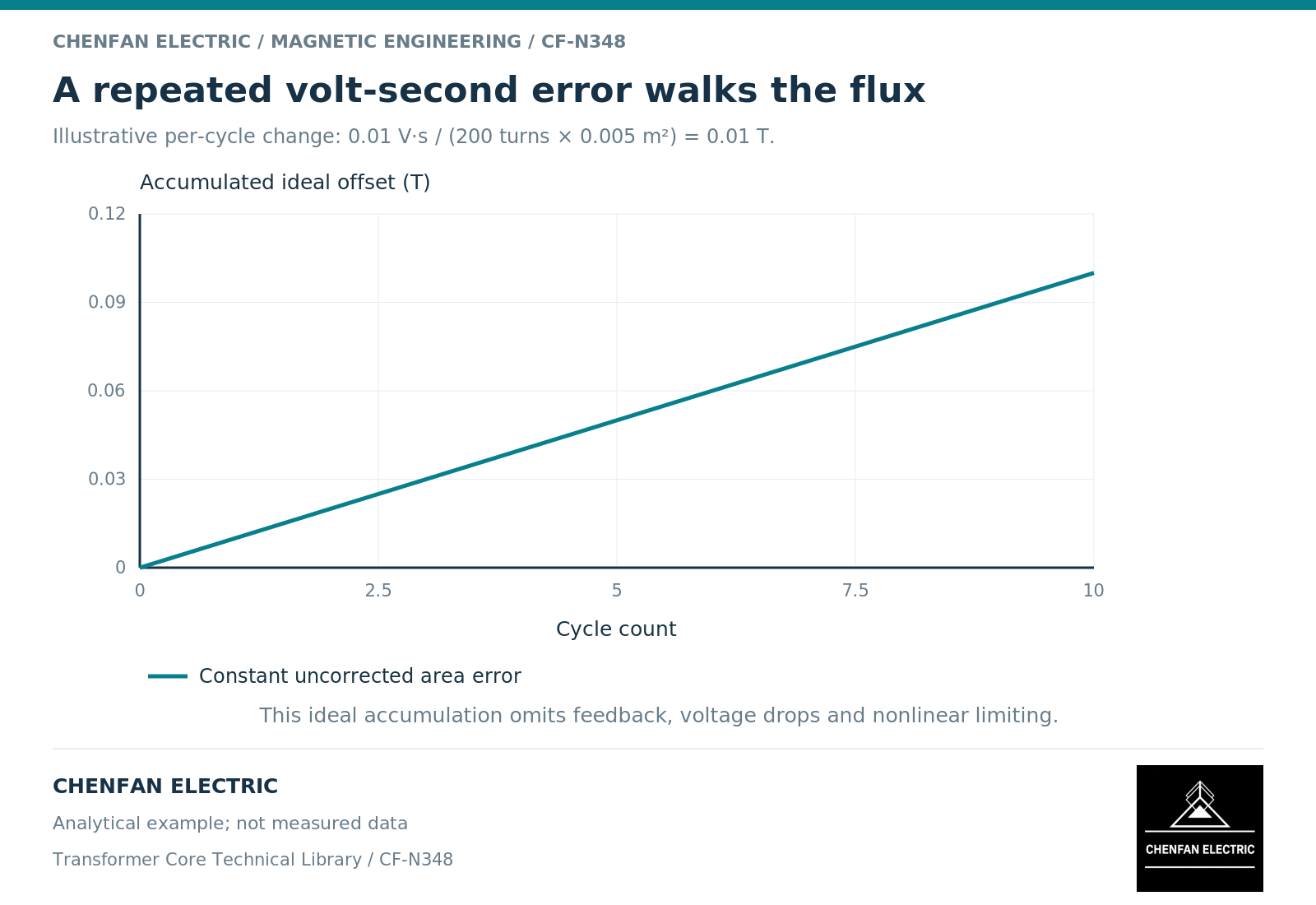
An illustrative calculation helps locate the issue. A net 0.01 volt-second per cycle across an ideal 200-turn winding changes flux by 0.00005 weber per cycle. With a net section of 0.005 square metre, that is 0.01 tesla per cycle before circuit feedback is considered. These invented values describe the integral error, not a prediction that physical flux will grow linearly forever.
Diagnose the boundary before proposing a remedy
A transformer at the output of a filter may not experience the same pulse imbalance as a transformer directly connected to a switching bridge. The waveform location, connection and operating mode must be clear.
Likewise, current asymmetry can arise from measurement offset or an initial transient. Compare the cumulative induced-voltage integral across repeated cycles and inspect whether the starting point continues to move. Do not infer walking solely from one large first-cycle current peak.
The observation interval should include the control transition of interest. A steady-state record can miss a startup imbalance, while a short startup record may not establish a persistent condition.
Handover the evidence, not an unqualified label
| Evidence | Question it resolves |
|---|---|
| Transformer-terminal waveform | What excitation actually reaches the winding? |
| Circuit-drop treatment | What portion drives mutual flux? |
| Per-cycle signed integral | Is the trajectory moving between cycles? |
| Initial state | Is the offset inherited rather than accumulating? |
| Control-mode chronology | When does the imbalance arise or cease? |
Any corrective design or control decision belongs to the responsible system and equipment engineers. This article supplies no switching settings, reset-component dimensions or protection instructions.
The useful conclusion identifies the source of the imbalance, its duration and its effect on the magnetic envelope. It should not blame the core material for an undefined converter behavior, nor claim that a larger core alone resolves an unexamined volt-second imbalance. The complete circuit must provide a supported operating trajectory.
References
[1] Lloyd Dixon / Texas Instruments. Magnetics Design 1 – Introduction and Basic Magnetics.
[2] Lloyd Dixon / Texas Instruments. Magnetics Design 4 – Power Transformer Design.