

A utility-frequency transformer connected to a converter may see filtered near-sinusoidal voltage, a waveform with switching ripple or direct pulse-width-modulated excitation. These are different duties. Identify the actual voltage at the transformer winding before using a switching frequency or harmonic spectrum in the magnetic design.
Locate the transformer relative to the filter
Pulse-width modulation, or PWM, describes a switching method, not a complete transformer specification. The waveform at a converter bridge can differ substantially from the waveform after a filter and cable system.
The interface record should identify the measurement or calculation location, line-to-line versus phase voltage, common-mode components and the relevant operating modes. A bridge-side waveform cannot be assumed to appear unchanged across a transformer phase winding.
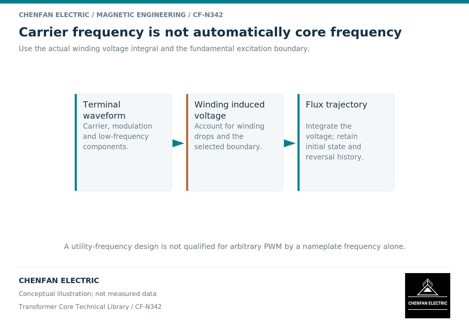
For magnetic excursion, integrate the induced voltage per turn. [1] For insulation and capacitive behavior, voltage edges and common-mode relationships can require additional assessment. These questions share a waveform source but do not use the same model or acceptance evidence.
Do not substitute carrier frequency for fundamental excitation
A switching carrier superimposed on a low-frequency voltage does not automatically allow the core to be designed as though the entire applied voltage alternated at the carrier frequency. The low-frequency voltage-time area still contributes to the main flux excursion.
An illustrative sinusoidal component at 50 hertz and a ripple component at 5 kilohertz have different flux weighting. For equal peak voltage amplitudes in an ideal winding, the higher-frequency component produces one hundredth of the flux amplitude. That does not imply one hundredth of every loss or dielectric effect.
The actual ripple waveform may contain multiple sidebands and non-sinusoidal edges. Preserve their timing or complex spectrum when the model needs them. A single total harmonic distortion number cannot reconstruct that waveform.
Assess magnetic, winding and insulation duties separately
A core-loss model needs a supported treatment of the resulting flux trajectory, including minor loops when relevant. A winding-loss model needs the current spectrum and conductor arrangement. An insulation assessment needs the applicable terminal and internal voltage stresses.
Switched-transformer design guidance distinguishes leakage effects, winding loss and magnetic excitation. [2] Its small-power examples are not qualification limits for a distribution or power transformer.
| Assessment | Principal input to preserve |
|---|---|
| Main flux excursion | Induced voltage-time waveform and turns |
| Core loss | Flux trajectory, material data and temperature |
| Winding loss | Current spectrum and winding geometry |
| Dielectric stress | Voltage edges, distribution and common-mode boundary |
| Thermal performance | Spatial losses, duration and cooling |
A favorable result in one row should not be used to close another row without supporting evidence.
Specify the operating envelope rather than “PWM compatible”
The technical package should include fundamental voltage and frequency, modulation range, relevant switching conditions, filter configuration, cable boundary and the actual transformer-terminal waveforms. Identify normal, startup and specified fault-related modes separately.
Where only a spectrum is provided, retain amplitudes, phase information where needed and the definition of each reference quantity. State whether values are peak or root-mean-square and whether they describe voltage or current.
The original equipment manufacturer can then determine whether the proposed transformer design is suitable and what verification is required. The core supplier’s role is to manufacture the evaluated magnetic geometry and material configuration within the agreed scope. A generic statement that a core is “for PWM” cannot replace that interface definition, and an educational discussion of the topic is not a claim of an existing converter-transformer product line.
References
[1] Lloyd Dixon / Texas Instruments. Magnetics Design 1 – Introduction and Basic Magnetics.
[2] Lloyd Dixon / Texas Instruments. Magnetics Design 4 – Power Transformer Design.