

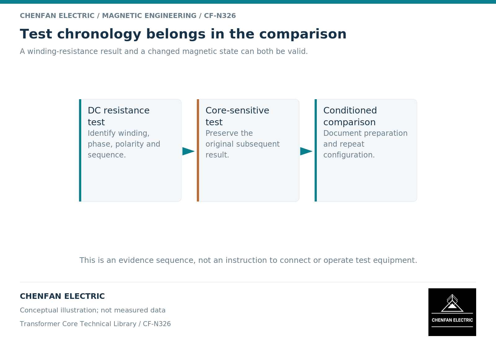
A direct-current winding-resistance test can alter the magnetic history relevant to subsequent core-sensitive measurements. [3] The important handover is not simply the resistance value: it is the test chronology, the later conditioning state and the configuration used for the comparison. Do not interpret a changed excitation response without that context.
Resistance and magnetic state are different outputs
The resistance test is intended to characterize an electrical winding quantity under its stated conditions. The applied current also produces magnetomotive force. Because a ferromagnetic core has history-dependent behavior, removing that current does not imply that every magnetic state variable returns to its previous value. [1]
A valid resistance measurement and a changed residual state can therefore coexist. There is no contradiction to resolve by discarding one of the observations.
Record which winding and phase were involved, the polarity convention, the relevant procedure and the sequence of measurements. The purpose is not to reconstruct a field test from memory, but to preserve enough history for the next engineer to interpret the result.
Identify which later measurement is being compared
Excitation current, induced-voltage behavior and low-frequency portions of a frequency-response comparison can depend on the magnetic boundary. Their sensitivity is not identical, and not every difference has the same cause.
Frequency-response analysis is a comparative method that also depends on repeatable measurement connections. Manufacturer guidance emphasizes comparison and configuration rather than treating one trace as a universal verdict. [2]
Before assigning a later discrepancy to remanence, check the reference unit or previous record, tap position, terminal state and measurement arrangement. A configuration mismatch can survive demagnetization because it was never a magnetic-history issue.
Preserve the before-and-after evidence
When an approved conditioning process is used before a repeat measurement, keep both results with their chronology. Do not retain only the more reassuring trace. The change itself is useful evidence about sensitivity to initial state.
The comparison should answer three separate questions: whether the test conditions were aligned, whether the response changed after conditioning and whether a discrepancy remains against the valid reference. Those questions require different evidence and should not be compressed into a single pass/fail comment.
| Record | Why it matters |
|---|---|
| Original resistance test | Defines the preceding electrical excitation |
| Original subsequent measurement | Preserves the observation that triggered review |
| Conditioning record | Defines the intentional change in magnetic history |
| Repeat measurement | Shows response under the revised starting condition |
| Technical disposition | Explains any remaining difference |
No universal residual-flux percentage can be assigned from the resistance result alone. The actual state depends on the assembly and its history, not merely on the fact that direct current was used.
Make test order visible in the final report
The report index should include a chronology rather than sorting every document only by test type. This helps a reviewer see that two measurements bearing the same date may have followed different histories.
For factory-to-site comparisons, retain the difference between the original equipment manufacturer’s test sequence and the receiving team’s later sequence. A bare-core magnetic record, an active-part record and a complete-transformer record should also remain separately identified.
The practical conclusion is disciplined: previous direct-current excitation is a relevant variable to check, not a convenient universal explanation. Once the history and configuration are aligned, the remaining evidence can support a more reliable assessment of the transformer rather than a debate over two numbers stripped of their test context.
References
[1] Cesare Tozzo / COMSOL. Modeling Ferromagnetic Materials in COMSOL Multiphysics.
[2] OMICRON. Sweep Frequency Response (SFRA).
[3] OMICRON. TESTRANO 600 Brochure.