

Terminal-voltage records can support an estimate of residual flux, but integration does not make an unknown initial condition disappear. The estimate must account for winding voltage drops, channel offset, record duration and the relation between terminal voltage and the modeled mutual flux. Report an uncertainty range when those inputs are not fully known.
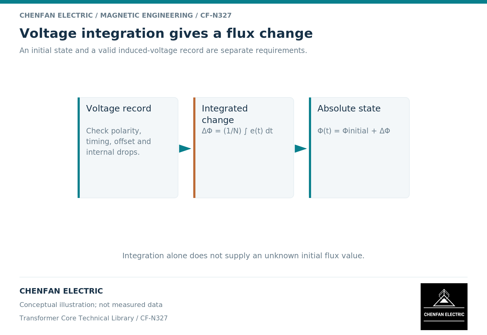
Integrate the correct quantity
For N turns, the change in linked flux is the time integral of induced voltage divided by N. [1] To use a terminal record, establish whether the terminal voltage is an adequate approximation to that induced voltage for the event being analyzed.
During current decay or strongly nonlinear behavior, resistance and leakage-related drops may matter. A circuit model can help estimate them, but introduces its own parameter uncertainty. The classical transformer-model discussion shows why the nonlinear branch and leakage circuit must be located consistently. [2]
The integration reference also matters. A record beginning after the interruption has already started may omit part of the flux change. A beautifully integrated partial record does not recover the missing interval automatically.
A small voltage bias becomes a growing flux error
An illustrative constant measurement offset of 0.2 volt integrated for 0.5 second produces 0.1 volt-second of error. With 100 turns, that becomes 0.001 weber. If the relevant net area is 0.010 square metre, the corresponding average density error is 0.1 tesla.
These invented values demonstrate error propagation; they are not a statement about any instrument’s accuracy. The calculation shows why a visually small baseline error can matter over a long integration interval.
Blindly subtracting a mean value is not always a cure. Depending on the event, that operation may remove a genuine low-frequency component. State the baseline method, justify the interval used and show how alternative defensible choices change the result.
Distinguish change in flux from absolute residual flux
Voltage integration directly gives a change relative to the starting state. An absolute residual estimate needs an additional reference or a supported assumption about that starting state. Without it, the correct output may be a family of possible trajectories.
For three-phase cores, the estimated limb states must also fit the topology and return paths. Independent channel processing should not create a state vector that violates the magnetic model’s continuity constraints.
Keep phase labels, polarity and time alignment through every processing step. A phase swap or sign inversion can create a plausible-looking but physically incorrect residual pattern.
Deliver a reproducible estimation record
The useful evidence package includes the raw waveform, scaling, sampling information, time window, turn count, tap position and the voltage-drop treatment. Provide the processed induced-voltage estimate and the integration method as separate records.
| Uncertainty source | Effect to examine |
|---|---|
| Channel offset | Accumulated integral drift |
| Missing event interval | Unobserved flux change |
| Winding-drop approximation | Difference between terminal and induced voltage |
| Initial-state assumption | Absolute offset of the trajectory |
| Phase alignment | Consistency of the multi-limb state |
A sensitivity interval should be carried into the switching study rather than collapsed into an unjustified exact value. Where the uncertainty dominates the result, better event data may be more valuable than a more elaborate hysteresis model.
The estimate should ultimately be labeled as an estimate with a stated basis. It can inform a controlled-switching or inrush assessment without being presented as a direct magnetic measurement or a guaranteed state for the next energization.
References
[1] Lloyd Dixon / Texas Instruments. Magnetics Design 1 – Introduction and Basic Magnetics.
[2] Manitoba Hydro International / PSCAD. The Classical Approach.