

“Close the gap as much as possible” is not a complete step-lap assembly instruction.
It can conceal a disagreement about which gap is being measured.
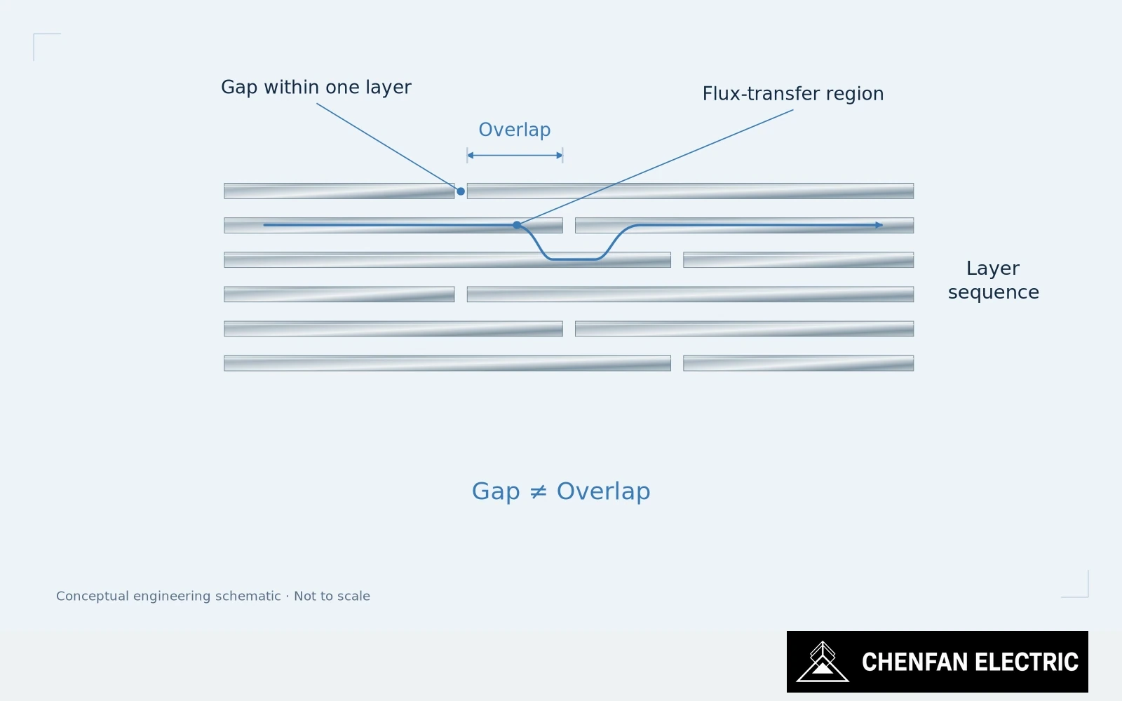
Distinguish end clearance from overlap
In a stepped joint, the end clearance within a layer and the overlap provided by adjacent layers are different geometric features. Both interact with the sequence of sheets, their alignment and the intended path for flux transfer.
An excessive unintended clearance can increase local reluctance. But forcing sheet ends together is not a substitute for achieving the designed geometry. If the lengths or angles do not fit, forcing closure can introduce buckling, displaced steps or local contact damage while producing an attractive measurement at one visible edge.
The magnetic circuit sees the whole joint region. Flux can redistribute between neighbouring sheets and depart from the preferred rolling direction. The result depends on the available transfer region and local induction, not on a single gap number viewed independently of the lap pattern.
Investigate the cause of abnormal fit
For inspection, first define the feature. State the location, assembly condition, measuring method and the approved nominal or tolerance. A feeler-gauge result at an accessible outer sheet should not be reported as though it describes every internal layer.
Then check the features that can explain an abnormal gap: cut length, mitre angle, packet position and sequence. The corrective action may belong at cutting or datum control rather than at the operator’s hand during final closure.
A design change to the joint should be evaluated as a geometry change. Keep material and excitation comparable, examine the relevant loss and current response, and verify that the revised arrangement remains manufacturable across the stack. Do not award an improvement merely because the new drawing contains a smaller number.
Verify the approved joint without forced closure
There is no universal optimum gap that can be copied from one transformer family into another. Core size, joint topology, sheet grouping and the design operating point all affect the assessment. The supplier and designer should agree the intended geometry rather than negotiate a cosmetic zero.
A useful acceptance photograph shows the sequence and reference features needed to interpret the measurement. A close-up containing only a ruler and one dark line is weak evidence.
The objective is a repeatable, unstressed realization of the approved joint. Where a gap is outside that definition, correct its cause. Do not hide a dimensional mismatch by forcing the steel to look closed.
Practical takeaway
A small visible gap can conceal incorrect overlap or forced assembly.
Chenfan Electric manufactures custom transformer cores according to customer drawings. Where applicable to the specified material and core design, agreed process controls include burr height below 0.02 mm and stacking factor above 97%. Measurement methods and acceptance conditions are defined for each order.