

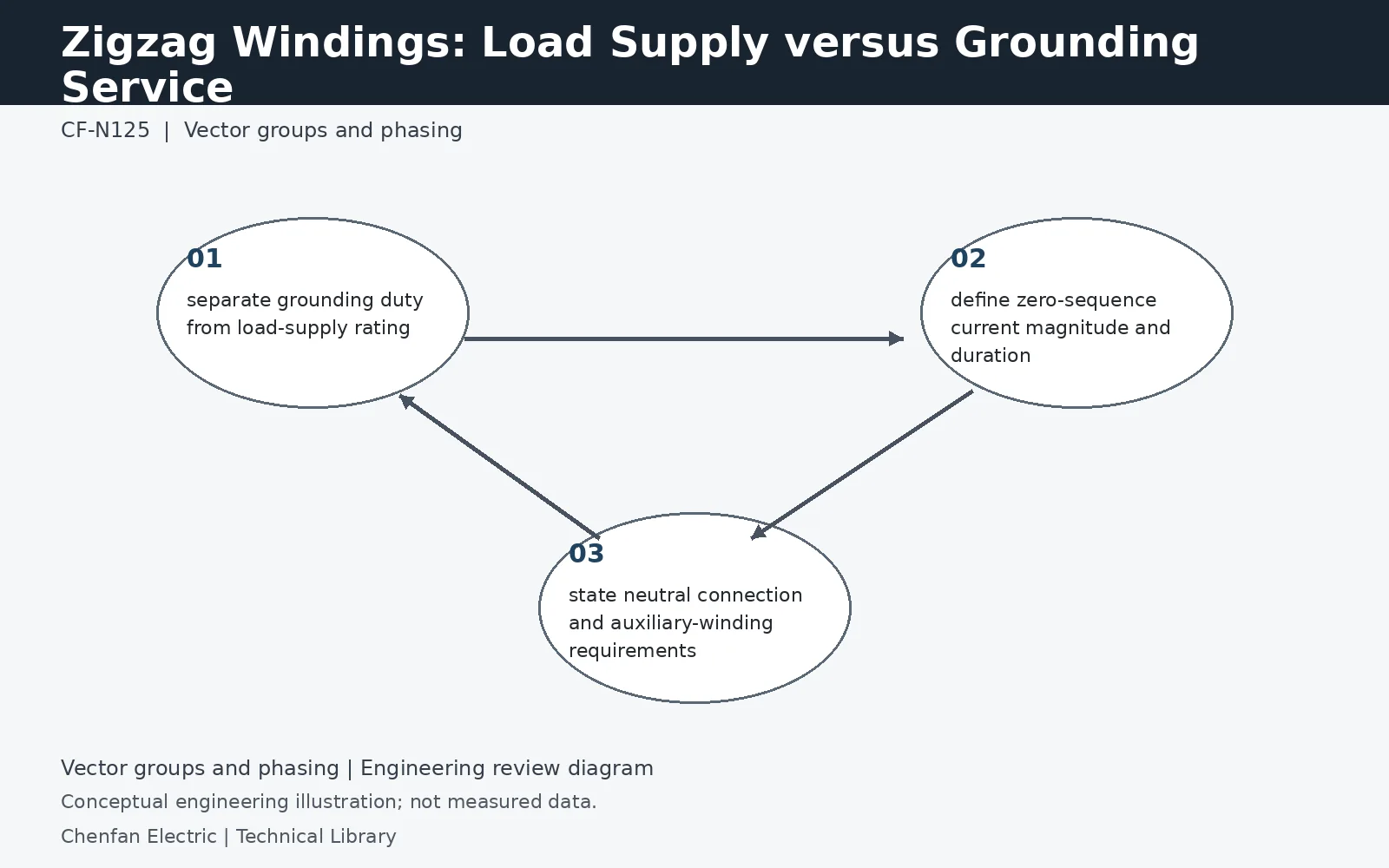
A zigzag winding may be designed mainly to provide a grounding path, to supply load, or to combine both functions. Those uses create different continuous and short-time current duties and different thermal design questions. The specification must therefore state the zero-sequence grounding duty separately from any auxiliary or phase load rating, and must identify how the neutral is connected to the grounding device.
Neutral current is not a three-phase load rating
For a balanced zero-sequence terminal condition, the three equal in-phase currents satisfy In = 3I0. An illustrative 300 A neutral duty therefore corresponds to 100 A in each external phase under that condition. It does not describe a 300 A balanced positive-sequence load supply. Internal zigzag coil currents and voltages must be interpreted through the winding design. Procurement should state the grounding current and time directly, rather than converting an unfamiliar grounding rating into a conventional distribution-transformer kVA without the manufacturer's definition.
Specify continuous heating as well as fault duration
A grounding transformer can carry continuous neutral unbalance even when no fault is present. Harmonic components and any auxiliary winding add further heating. If the unit must supply station service during a ground fault, that simultaneous duty belongs in the specification. Separate short-time current, repetition interval, pre-fault loading and recovery assumptions. A short-time rating established from a cool starting condition cannot automatically be applied repeatedly while an auxiliary load keeps the winding temperature elevated.
Confirm the complete grounding interface
Identify bus voltage, zero-sequence impedance, connection arrangement, neutral grounding device and the protection used to detect loss of the grounding path. The zigzag design does not determine the resistor rating or clearing policy on its own. Where an auxiliary secondary is provided, define its voltage, load rating, phasing and insulation separation independently. Ask the supplier to issue one combined duty schedule showing permissible simultaneous conditions. That is more useful than unrelated nameplates whose maximum values cannot all be used together.
Technical reference framework
[1] IEC 60076-8:1997 — Application guide.
[2] IEEE C57.105-2019 / Cor 1-2023 — Three-phase transformer connections.
[3] Post Glover GT110-08 — Zig-zag grounding transformers.