

Short answer
Underground overhead secondary distribution choices trade fault exposure against repair difficulty and thermal behaviour. Overhead low-voltage lines are exposed to trees, wind, lightning and vehicles, so they fault more often, but faults are easy to see and repair. Underground cables fault far less often, but locating and repairing a fault takes longer. In an illustrative comparison, overhead lines with 0.5 faults per km a year at 2 hours each, and underground cables with 0.05 faults at 12 hours each, give about 1.0 and 0.6 hours of unavailability per km a year. Thermal limits differ: underground cables depend on soil thermal resistivity and grouping, overhead conductors on sag clearance and ambient conditions. The choice also determines transformer type and site needs. Any comparison must use the same load, service area and boundary assumptions.
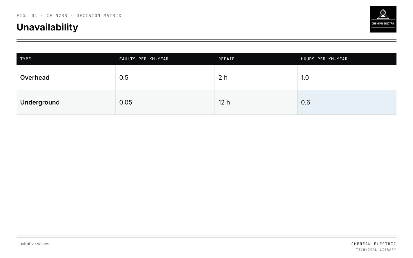
Fault exposure and repair
| Type | Faults per km-year | Repair | Hours per km-year |
|---|---|---|---|
| Overhead | 0.5 | 2 h | 1.0 |
| Underground | 0.05 | 12 h | 0.6 |
Illustrative example. Same service area. Overhead: 0.5 faults per km per year, mean repair 2 h. Underground: 0.05 faults per km per year, mean repair 12 h. Values chosen for demonstration.
overhead: 0.5 × 2 = 1.0 h per km per year
underground: 0.05 × 12 = 0.6 h per km per year
Underground is better here, but a cable with poor records or long excavation permits could reverse the result. Each utility should use its own data.
| Aspect | Overhead | Underground |
|---|---|---|
| Fault rate | Higher | Lower |
| Fault location | Visible | Needs equipment |
| Repair | Fast | Excavation |
| Weather events | Many simultaneous faults | Fewer |
| Flooding | Less affected | Water ingress risk; see water-blocking boundaries |
Thermal limits
- Underground: soil thermal resistivity, depth, grouping, drying around cables in summer.
- Overhead: conductor temperature limited by sag and clearance; wind cooling helps.
- Ratings for the same conductor size differ; underground often needs larger sections.
Transformer and site
| Choice | Transformer | Site |
|---|---|---|
| Overhead | Pole-mounted, smaller units | Pole space, clearances |
| Underground | Pad-mounted or vault | Ground space, access, drainage |
Pad-mounted equipment brings separable connectors and compartments; see loadbreak versus deadbreak separable connectors. Siting and reach depend on cable routes; see transformer siting and service reach.
Fair comparison
Many published comparisons differ mainly because their assumptions differ, not because one system is inherently better. A fair study fixes the following inputs for both options.
- Same load and growth assumptions.
- Same service boundary, including customers at the edge.
- Same reliability metrics and data period.
- Life-cycle costs with the same discount rate and lifetime.
- Local conditions: trees, soil, flooding, permits.
Restoration options also differ; see tie-switch placement for feeder restoration.
What this article does not cover
It does not use country or regional labels as evidence for either choice.
Where this reasoning stops. Fault rates and repair times are illustrative; use local records.
Practical takeaway
Compare overhead and underground secondaries on the same load and area using local fault rates and repair times, account for different thermal limits and transformer types, and include life-cycle costs and site conditions.
Reference framework
- IEEE 1366, Guide for electric power distribution reliability indices.
- IEC 60287, Electric cables: calculation of the current rating.