


Transformer Core Engineering Notes · CF-N290
Vibration isolation changes the mechanical support path, while electrical bonding must maintain the required protective connection. The two interfaces must be designed together. Adding resilient pads without reviewing movement, anchorage, terminal connections and bonding can solve one vibration path while introducing another mechanical or electrical problem.
Identify the vibration path and objective
Separate structure-borne vibration from airborne sound and define the location where improvement is required. An isolator should be selected for the actual mass distribution, excitation and support conditions by a qualified designer. A soft pad is not automatically an effective isolator. The assessment should also consider stability and the movement permitted at connected conductors, pipes and nearby equipment.
Check parallel mechanical paths
Rigid conduits, bus connections, pipework or poorly arranged restraints can bypass the intended isolation. Review the installed assembly rather than evaluating the support pads alone. Any flexible interface must retain its electrical or fluid function while accommodating the approved movement. A successful component demonstration does not prove the room will experience the expected reduction once all connections and restraints are installed.
Preserve the protective bonding function
The electrical designer must provide a bonding arrangement appropriate to the equipment and applicable requirements. Do not rely on incidental metal contact across an isolator, and never remove a required protective bond to reduce vibration. A flexible bond needs adequate electrical capability and movement allowance. Its routing should be coordinated with the isolation design without weakening the protective function.
Accept the complete installed behavior
Verify the approved support, restraint and bonding arrangement and compare vibration or sound observations under defined operating conditions. Record what was measured and where; reduced vibration at one point is not automatically a reduction in all sound levels. Later changes to cables, supports or anchorage should trigger an interface review. Keep the final arrangement documented so maintenance does not inadvertently short-circuit the mechanical isolation path.
| Review item | Evidence to request | Boundary to preserve |
|---|---|---|
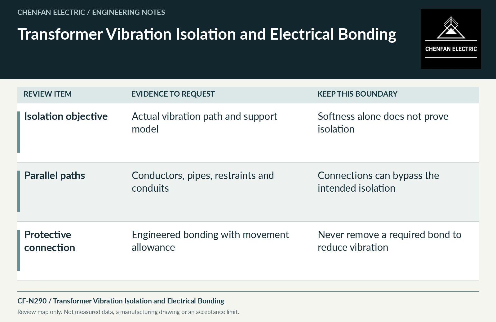
| Isolation objective | Actual vibration path and support model | Softness alone does not prove isolation |
| Parallel paths | Conductors, pipes, restraints and conduits | Connections can bypass the intended isolation |
| Protective connection | Engineered bonding with movement allowance | Never remove a required bond to reduce vibration |
References and scope
- IEC 60076-10:2016 — Determination of sound levelsPublic standard abstract · Transformer/reactor sound measurement; operating conditions and sound-power/sound-pressure distinctions matter.
- IEC 60076-1:2011 — Power transformers: GeneralPublic standard abstract · General transformer scope, interfaces and controlled equipment specification.
- Electrical Connections for Power Circuits (FIST 3-3)Historical technical manual · Electrical-joint and connection principles; not a universal torque table.