

A tuned mass damper adds a secondary moving mass whose response interacts with a structural mode. Its best result often occurs near a chosen frequency. The transformer structure, however, can change with temperature, liquid state, contact stiffness or assembly variation.
Evaluate a frequency band and a range of structural states. A deep reduction at one design point is less useful if a modest shift moves the excitation onto a neighboring peak.
Start with a transparent model
For a linear two-degree-of-freedom illustration, define primary modal mass M, stiffness K and damping C, and attached damper mass m, stiffness k and damping c. The damper’s uncoupled natural angular frequency is √(k/m). Its tuning relationship is with the targeted structural mode, not necessarily with the nominal electrical frequency alone.
The attachment changes the coupled modes. It can split a resonance and create an antiresonance at a selected response location. That antiresonance is not a guarantee of low motion everywhere on the tank.
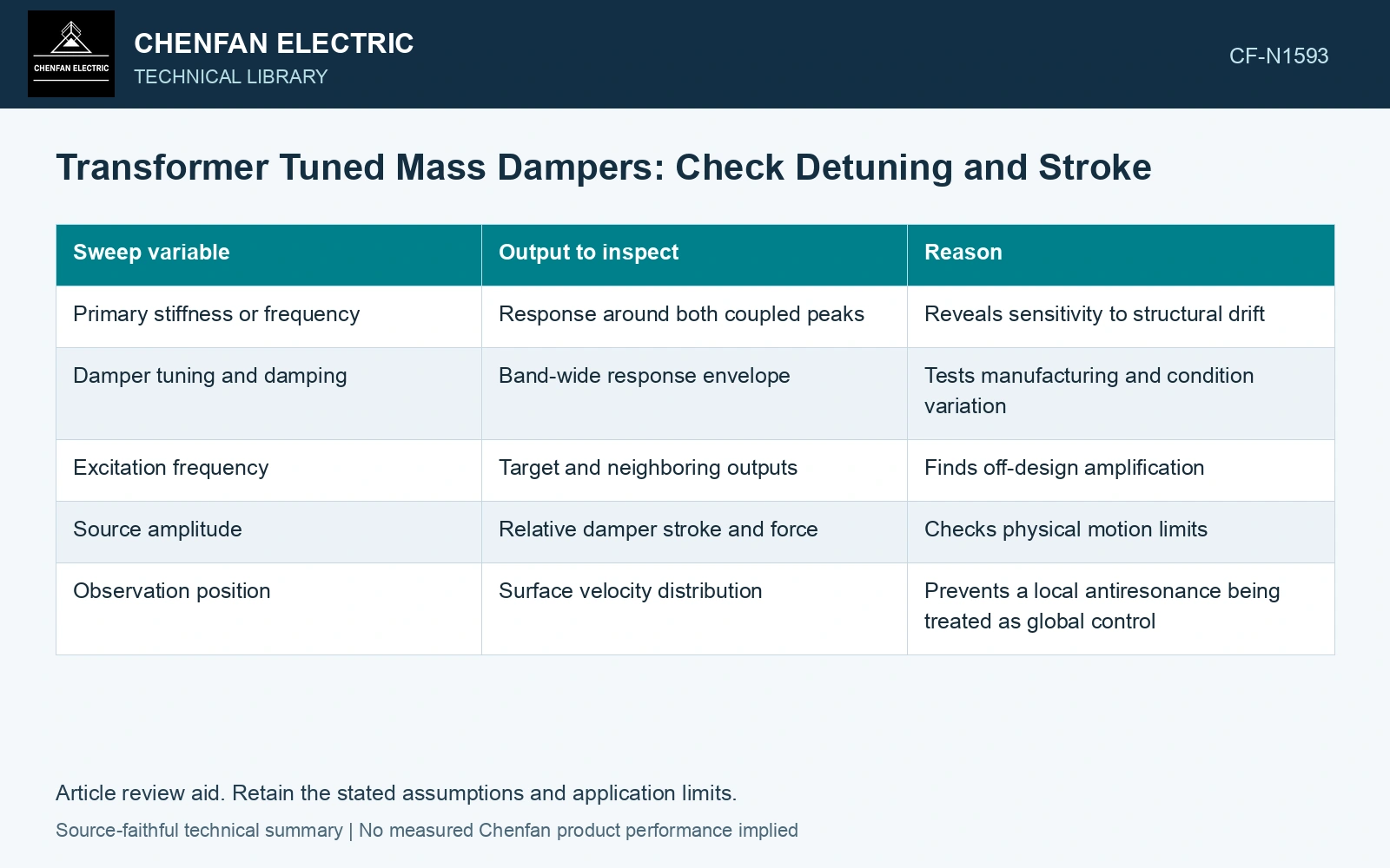
| Sweep variable | Output to inspect | Reason |
|---|---|---|
| Primary stiffness or frequency | Response around both coupled peaks | Reveals sensitivity to structural drift |
| Damper tuning and damping | Band-wide response envelope | Tests manufacturing and condition variation |
| Excitation frequency | Target and neighboring outputs | Finds off-design amplification |
| Source amplitude | Relative damper stroke and force | Checks physical motion limits |
| Observation position | Surface velocity distribution | Prevents a local antiresonance being treated as global control |
Check the attachment’s motion
The relative displacement between damper and structure determines stroke. An acceptable primary response can coexist with large secondary motion. Check the allowable travel, mounting force and the conditions under which stops or nonlinear behavior occur.
Use the actual mounting region. A damper attached near a node of the target mode may couple weakly. A simplified modal model also needs a justified effective mass and mode shape at the attachment point; the full physical transformer mass is not a substitute for modal mass.
Compare the untreated and treated responses using the same source and boundary assumptions. Retain frequency resolution sufficient to capture narrow peaks. A coarse sweep can skip the very response increase that matters under detuning.
Verify the acoustic consequence
Reduced motion at the attachment point does not automatically reduce total radiated sound. The changed tank mode can redistribute velocity and alter phase cancellation. Evaluate or measure the relevant surface motion and acoustic outputs over the same band.
Reserve an off-design condition for validation rather than selecting all model parameters from the favorable tuning test. If the model predicts that condition poorly, reassess contact, damping and source assumptions before claiming a broad operating benefit.
A defensible damper choice has a documented response envelope and adequate physical motion capability. The decision rests on its performance across expected conditions, including the peaks it introduces, rather than the depth of one attractive notch.
Compare the notch with a neighboring frequency and stroke
Assume a primary modal mass of 100 kg at 100 Hz with 2% damping, and a 5 kg damper tuned to 100 Hz with 10% damping; apply a 100 N peak harmonic force. Use stiffness k = m(2πf)² and damping c = 2ζm(2πf) in the coupled two-mass equations. At 100 Hz, solved primary motion falls from 63.33 to 8.61 μm peak, but damper relative stroke is 43.04 μm. At 90 Hz, primary motion rises from 13.10 to 18.70 μm, or 3.09 dB. Select against the complete response and stroke envelope; the large tuned-frequency improvement conceals off-tune amplification [1]. Judge the acoustic outcome using defined transformer and cooling-device sound conditions [2]. The frequency-domain pressure field and its structural coupling require the stated acoustic boundary conditions [3].
References
- Sönnerlind, H., Damping in Structural Dynamics: Theory and Sources, COMSOL, 14 March 2019.
- IEC, IEC 60076-10:2016, Power transformers – Part 10: Determination of sound levels, 2016, official public scope.
- COMSOL AB, Acoustics Module User’s Guide: The Pressure Acoustics, Boundary Elements Interface, version 6.3.