


Transformer Core Engineering Notes · CF-N251
Top-oil temperature describes one part of a transformer’s liquid temperature field. The winding hot spot describes the hottest relevant conductor or insulation location under a specified operating condition. They answer different questions. A comfortable top-oil reading does not, by itself, establish that every winding region remains within its permitted temperature.
Locate the temperature being discussed
Identify the sensor location, its immersion arrangement and whether the displayed value is measured or calculated. Oil at a thermometer pocket is not necessarily the oil immediately surrounding the hottest winding section. Similarly, an average winding temperature obtained from resistance is not a local maximum. Keep these quantities separately labelled in guarantees, test reports and monitoring screens so that a convenient available signal is not mistaken for the required design quantity.
Follow the load and cooling history
Winding and bulk-liquid temperatures do not necessarily change at the same rate after a load step. Their relationship also changes with cooling stages and internal flow. Comparing isolated readings from different times can therefore be misleading. Request synchronized load, ambient, cooling-state and temperature records. A useful analysis explains the response during the transition, rather than checking only whether the final top-oil value looks familiar.
Understand the hot-spot evidence
A thermal model estimates a hot spot from its assumptions and inputs. A fibre-optic sensor measures its own installed location. Neither should be described as an unrestricted measurement of the entire winding. Review how the critical location was selected and how model predictions were checked against appropriate tests. When geometry or duct arrangements change, the old relationship between top oil and the winding hot spot may need to be reassessed.
Specify the decision each signal supports
Define the temperatures used for cooling control, alarms, loading assessment and insulation ageing calculations. Setpoints must reflect the OEM’s design and the applicable protection philosophy, not an internet rule of thumb. The current mineral-oil loading guides and the IEEE temperature-measurement guide provide relevant frameworks. They do not turn a single observed top-oil value into permission to increase loading without checking the complete unit and operating conditions.
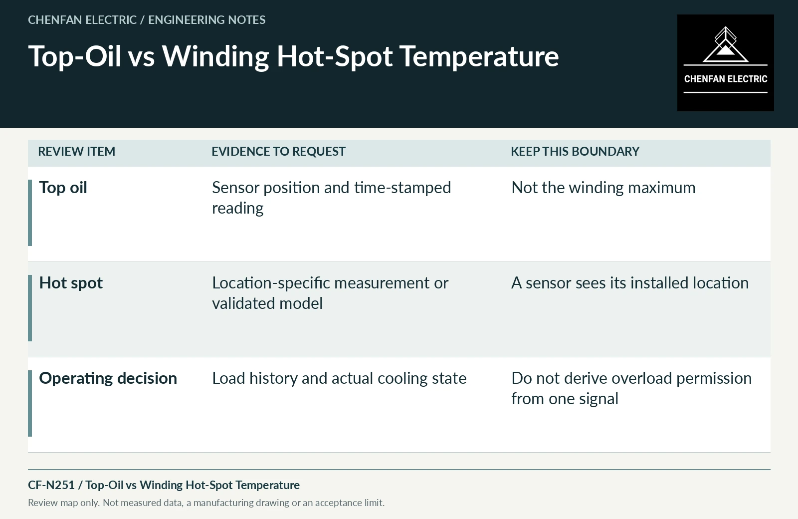
| Review item | Evidence to request | Boundary to preserve |
|---|---|---|
| Top oil | Sensor position and time-stamped reading | Not the winding maximum |
| Hot spot | Location-specific measurement or validated model | A sensor sees its installed location |
| Operating decision | Load history and actual cooling state | Do not derive overload permission from one signal |
References and scope
- IEEE C57.165-2024 — Temperature Monitoring of Liquid-Immersed TransformersPublic standard abstract · Temperature-monitoring methods for liquid-immersed transformers and their measurement/model boundaries.
- IEEE C57.91-2025 — Loading Mineral-Oil-Immersed Transformers and Step-Voltage RegulatorsPublic standard abstract · Mineral-oil loading, thermal duty and loading beyond nameplate; do not transfer the scope automatically to ester or dry-type equipment.
- IEC 60076-7:2018 — Loading guide for mineral-oil-immersed power transformersPublic standard abstract · Mineral-oil transformer loading and thermal-ageing framework, not a universal asset-life prediction.