

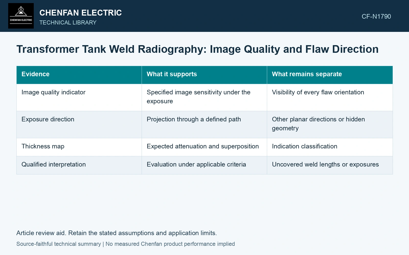
A radiograph records the attenuation along its beam paths. Tube, seam or corner geometry can superpose thickness, and a planar flaw can have an unfavorable orientation to the beam. Image-quality evidence is necessary but does not eliminate those physical limitations. [1]
Record source, detector and component positions with the weld ID. Mark the material traversed by each relevant beam path. The interpretation should refer to this exposure geometry, not only to a cropped image.
| Evidence | What it supports | What remains separate |
|---|---|---|
| Image quality indicator | Specified image sensitivity under the exposure | Visibility of every flaw orientation |
| Exposure direction | Projection through a defined path | Other planar directions or hidden geometry |
| Thickness map | Expected attenuation and superposition | Indication classification |
| Qualified interpretation | Evaluation under applicable criteria | Uncovered weld lengths or exposures |
Match the defect to the beam
A pore changes the traversed material differently from a thin planar discontinuity. A planar feature aligned unfavorably can produce weak contrast even in an otherwise acceptable image. Use demonstrated geometry and complementary evidence where required by the examination plan.
Do not classify every image indication as porosity without checking weld geometry and image artifacts. Likewise, an image-quality pass is not an acceptance pass for the weld; acceptance follows the specified criteria.
Choose NDT using material, weld thickness, welding process, quality requirements and demonstrated coverage. NDT acceptance levels are not a detailed one-to-one translation of weld quality levels. [2]
Compare beam paths through the joint
Assumptions: a 6 mm plane-parallel steel section is exposed at 0° and 60° from its normal. Beam-path thicknesses are 6 mm and 6/cos60° = 12 mm. Suppose the approved exposure setup is demonstrated only for 4–10 mm penetrated steel. The normal exposure falls within its range; the oblique path exceeds it by 2 mm and cannot use that setup’s demonstration without reassessment. An image-quality result still cannot prove every planar-flaw orientation detectable. Resolve the actual projection, superposition and complementary coverage in the examination plan rather than treating the IQI as a complete flaw-coverage certificate.
References
- U.S. Federal Highway Administration, Bridge Welding Reference Manual, FHWA-HIF-19-088, 2019.
- ISO, ISO 17635:2025, Non-destructive testing of welds — General rules for metallic materials.