

Weld repair near a tank flange changes the local thermal cycle and can alter sealing geometry. Removing the defect is one task; retaining flange flatness, bolt alignment and the specified gasket surface is another. [1]
Map the repair excavation and weld length relative to the sealing face. Keep the original dimensions, restraint and repair procedure with that map. The relevant dimensional boundary may extend beyond the visibly repaired area.
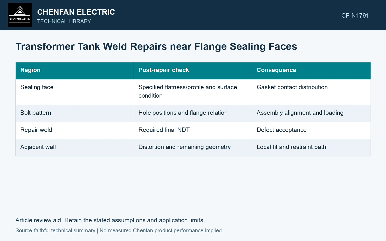
| Region | Post-repair check | Consequence |
|---|---|---|
| Sealing face | Specified flatness/profile and surface condition | Gasket contact distribution |
| Bolt pattern | Hole positions and flange relation | Assembly alignment and loading |
| Repair weld | Required final NDT | Defect acceptance |
| Adjacent wall | Distortion and remaining geometry | Local fit and restraint path |
Measure the final restrained state
Dimensions before cooling or while temporary fixtures remain may differ from the finished tank. Use the reference state specified by the drawing and inspection method. Mark any machining or corrective fabrication as a further revision that needs its own final checks.
Do not use gasket compression to conceal an unresolved flatness departure. A sealing system can accommodate only the conditions established by its design, and a leak test does not define a new dimensional allowance.
Choose NDT using material, weld thickness, welding process, quality requirements and demonstrated coverage. NDT acceptance levels are not a detailed one-to-one translation of weld quality levels. [2]
Separate flange flatness from seam acceptance
Assume the repair drawing permits 0.8 mm flatness deviation in its stated final measurement condition. The flange measures 0.5 mm before repair and 1.2 mm after cooling and fixture release. The final result exceeds that assumed design criterion by 0.4 mm. Resolve the sealing interface even if the weld examination itself passes.
References
- U.S. Federal Highway Administration, Bridge Welding Reference Manual, FHWA-HIF-19-088, 2019.
- ISO, ISO 17635:2025, Non-destructive testing of welds — General rules for metallic materials.