

Reverse real-power flow changes the sign of an export reading. It does not make winding current disappear. An export controller therefore needs a current and thermal assessment that includes the reactive-power duty and the voltage at which the transformer is operating. [1] [2]
Start with a defined sign convention
Specify which direction is positive for both P and Q at the transformer measurement boundary. The signs help interpret network behavior, but current magnitude depends on their combined effect. For balanced sinusoidal three-phase operation, I = √(P² + Q²)/(√3 V), using watts, vars, line-to-line RMS volts and amperes. This relation is a first-pass electrical check, not a model of unbalanced or harmonic heating.
At fixed voltage, a permissible current Iₗ defines P² + Q² ≤ 3V²Iₗ². Both import and export real power appear through P². The permissible current may still depend on thermal state, cooling and duration; the circle is not a universal operating capability curve.
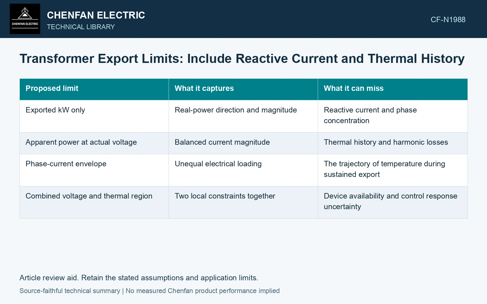
| Proposed limit | What it captures | What it can miss |
|---|---|---|
| Exported kW only | Real-power direction and magnitude | Reactive current and phase concentration |
| Apparent power at actual voltage | Balanced current magnitude | Thermal history and harmonic losses |
| Phase-current envelope | Unequal electrical loading | The trajectory of temperature during sustained export |
| Combined voltage and thermal region | Two local constraints together | Device availability and control response uncertainty |
Use the interval history, including the direction change
Evaluate how long export continues and what load preceded it. A transformer transitioning from sustained import to export retains its thermal state. Reporting the export period as a fresh operating case can omit the hottest starting condition. Cooling status and ambient assumptions should travel with the same timeline.
Do not infer identical total losses solely from equal current magnitude in the two directions. Compare the actual voltage, tap, waveform and other relevant conditions. The basic current-squared winding-loss argument identifies one contribution, while the installed transformer and operating state define the fuller assessment.
Intersect the electrical and network constraints
An export reduction may satisfy current limits but fail to resolve a voltage condition, or a reactive-power action may change voltage while consuming device and transformer current margin. Evaluate the proposed P–Q point against both constraints and the resource capability.
Assume a balanced port, positive P defined as import, and a 500 A current cap. At export P = −300 kW and Q = +100 kvar, current is 456.44 A at 400 V line-to-line but 480.46 A at assumed 380 V. At 380 V and Q = +200 kvar it becomes 547.82 A, failing the cap. The current-circle screen then permits |P| ≤ √[3(380 × 500)² − 200,000²] = 261.34 kW. Restrict export magnitude or net reactive transfer, then check voltage/phase harmonics and the inherited thermal state. Power direction does not cancel winding current.
Record the binding constraint with each export allowance. A limit imposed by voltage should not be reported as a transformer thermal rating, and a temporary thermal allowance should not become a permanent export entitlement. The completed envelope should explain which condition moves its boundary and which measurement verifies the dispatched response.
References
- A. Jain and M. Karimi-Ghartemani, Mitigating Adverse Impacts of Increased Electric Vehicle Charging on Distribution Transformers, Energies 15, 9023, 2022. DOI: 10.3390/en15239023.
- IEC, IEC 60076-7:2018, Power transformers – Part 7: Loading guide for mineral-oil-immersed power transformers.