

Short answer
Transformer GIS phase mapping is a common source of power flow errors. Geographic information systems store lines and devices by location and attributes; power flow needs electrical connectivity and the phase each transformer connects to. Lines that touch on a map may not be connected, crossing conductors may be on different circuits, and phase labels may be missing or wrong. In an illustrative network with 1,200 single-phase transformers and a 3 % phase error rate, about 36 units are assigned to the wrong phase, which distorts phase loading and voltage results. Topology checks catch many such errors automatically: a transformer labelled phase B cannot be connected to a line section that carries only phases A and C. Missing phase information should be preserved as missing rather than filled in by default, and corrections should flow back to the GIS.
Spatial versus electrical
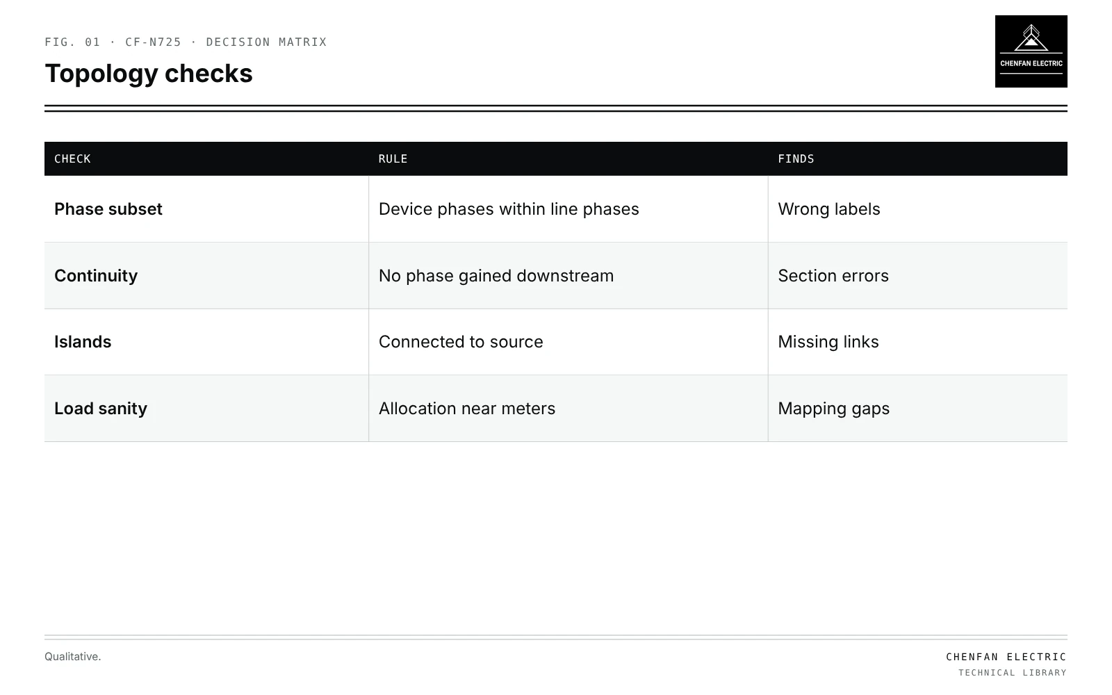
| Check | Rule | Finds |
|---|---|---|
| Phase subset | Device phases within line phases | Wrong labels |
| Continuity | No phase gained downstream | Section errors |
| Islands | Connected to source | Missing links |
| Load sanity | Allocation near meters | Mapping gaps |
| GIS feature | Electrical meaning |
|---|---|
| Lines touching | May or may not be connected |
| Lines crossing | Usually not connected |
| Device near a line | Connection must be stated |
| Phase attribute | May be missing, outdated or default |
Conversion must use explicit connection attributes, not geometry alone.
Phase consistency checks
Illustrative example. Network of 1,200 single-phase transformers; field audit suggests 3 % have wrong phase labels. Values chosen for demonstration.
1,200 × 0.03 = 36 misassigned transformers
Automated checks:
- Phase subset: a device’s phases must be a subset of its upstream line’s phases.
- Continuity: a two-phase section cannot feed a three-phase device.
- Voltage class: device voltage must match line voltage.
- Islands: every device must connect to a source.
- Load sanity: transformers whose allocated load is far from meter totals.
Errors that pass topology checks, such as phase B labelled as phase C on a three-phase line, need measurement-based identification; see phase allocation using transformer-side smart-meter data.
Preserving missing information
- Unknown phase kept as unknown, flagged for field check.
- Defaults such as assigning all unknowns to phase A create artificial unbalance.
- Probabilistic assignment for studies, with sensitivity analysis, if field data are unavailable.
Effects of errors
| Error | Study effect |
|---|---|
| Wrong phase | False unbalance, wrong voltages |
| Missing connection | Island, unsupplied loads |
| False connection | Hidden parallel path; see normally open points without hidden parallel sources |
| Line-to-line loads lost | Delta loads modelled wrongly; see delta-connected loads |
Feedback loop
Corrections found in modelling or field audits should update the GIS, so that the next conversion does not repeat them. Load allocation and calibration depend on correct mapping; see calibrating transformer load allocation with AMI data.
What this article does not cover
General version control of as-built drawings is not covered here.
Where this reasoning stops. Error rates are illustrative; actual rates come from audits.
Practical takeaway
Convert GIS data using explicit connectivity, run phase-subset and island checks, keep unknown phases flagged rather than defaulted, and feed corrections back into the GIS.