

A cooling-water operating window is the intersection of thermal, hydraulic and material constraints. Continuity converts total flow to mean tube velocity [1]; heat duty and film performance need their own thermal model [2]. Mean velocity alone cannot establish an erosion or deposition limit.
For equal active tubes, mean tube velocity is u = Q/(nA), where Q is water volume flow in m³/s, n the number of flowing tubes and A one tube’s internal area in m². The result is m/s. Parallel pass arrangements and uneven flow require the actual circuit rather than the total tube count.
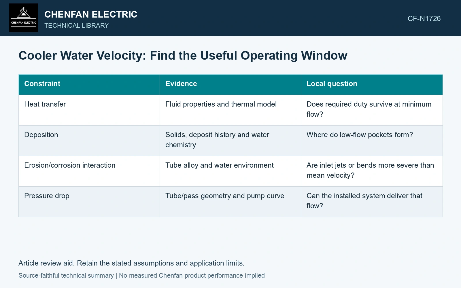
Place each constraint on the same velocity axis
| Constraint | Evidence | Local question |
|---|---|---|
| Heat transfer | Fluid properties and thermal model | Does required duty survive at minimum flow? |
| Deposition | Solids, deposit history and water chemistry | Where do low-flow pockets form? |
| Erosion/corrosion interaction | Tube alloy and water environment | Are inlet jets or bends more severe than mean velocity? |
| Pressure drop | Tube/pass geometry and pump curve | Can the installed system deliver that flow? |
Look beyond the straight tube
An inlet header can produce nonuniform entry flow. A partly plugged strainer or a blocked tube changes distribution. Erosion evidence should therefore be compared with the inlet region, bends and support details rather than assigned to the mean speed alone.
Check water solids and their variation. A clean-water material recommendation cannot automatically cover abrasive particles or a deposit that changes local chemistry. Likewise, changing the flow can affect vibration as well as heat transfer.
Place the minimum flow needed for thermal duty and the maximum allowed by the pump, material and local-flow qualification on the same tube/pass map. Use the tightest bounds rather than an unqualified universal velocity range. [1][2]
Calculate mean velocity before local review
Assume 0.010 m³/s water flow through 50 active tubes, each 0.020 m internal diameter. Mean tube velocity is 0.637 m/s. With 40 active tubes at the same total flow it becomes 0.796 m/s. Compare local distribution, pressure drop and material-specific erosion/fouling evidence before assigning an operating window.
For a separate hypothetical review, assume thermal duty requires at least 0.60 m/s and a material/geometry screen permits at most 0.75 m/s. With 40 tubes, Q must lie between 0.60 × 40π(0.020)²/4 = 0.00754 m³/s and 0.00942 m³/s. The assumed 0.010 m³/s exceeds that window. These illustrative bounds need replacement by the actual thermal and material qualification before selecting flow.
References
- U.S. Department of Energy, DOE-HDBK-1012/3-92, Thermodynamics, Heat Transfer, and Fluid Flow, Volume 3, 1992.
- U.S. Department of Energy, DOE-HDBK-1012/2-92, Thermodynamics, Heat Transfer, and Fluid Flow, Volume 2, 1992.