


Transformer Core Engineering Notes · CF-N276
A marshalling kiosk is an interface between transformer accessories and the site’s power, control and monitoring systems. A neat terminal layout is useful, but it does not prove functional completeness. Define signal meaning, supply responsibilities, environmental protection and failure behavior before checking that the terminal numbers match the drawings.
Build a signal schedule with functional meaning
For each contact, analog value or communication point, state its origin, normal condition, operated condition and intended destination. Distinguish alarm, trip, status and control functions. A contact described only as “temperature” leaves too much ambiguity. Include signal scaling and units where relevant, and identify whether the point represents a direct measurement, a calculated quantity or an equipment command.
Separate supply and circuit responsibilities
Identify AC and DC supplies, their nominal characteristics and which party provides protection and isolation. Review common dependencies between cooling, heaters, instruments and protection interfaces. A terminal available for a site supply does not prove the correct source is present or independent. Coordinate the transformer schematic with the station diagrams so a change in one package does not leave an essential function without its intended supply.
Protect the completed enclosure arrangement
Specify the intended environmental conditions and enclosure protection. Cable entries, drains, vents and field modifications must be consistent with the approved design. Internal condensation can remain relevant even when an enclosure has an ingress-protection rating. The OEM should define any required anti-condensation arrangement and its supply needs. Do not assume the empty cabinet’s catalogue rating proves the finished, cabled kiosk’s complete protection.
Test point-to-point and functional behavior
Acceptance should verify identification, wiring and the agreed functional response, including relevant failed-supply or failed-sensor cases. A continuity check alone does not demonstrate that an alarm is interpreted correctly by the receiving system. Record the as-built terminal plan, final settings and communication mapping. The handover should allow the owner to trace an observed indication back to the actual transformer device without relying on undocumented installer knowledge.
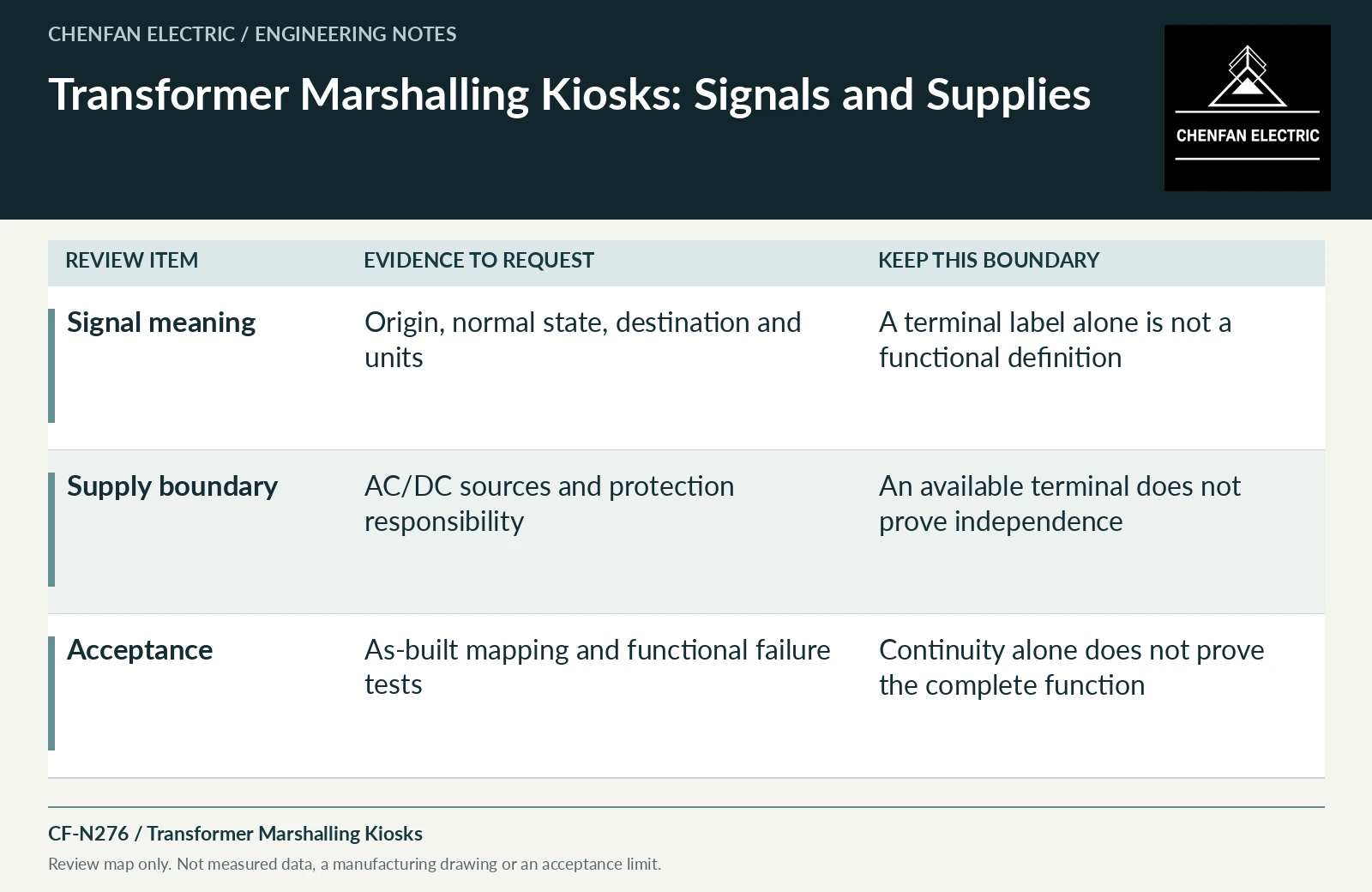
| Review item | Evidence to request | Boundary to preserve |
|---|---|---|
| Signal meaning | Origin, normal state, destination and units | A terminal label alone is not a functional definition |
| Supply boundary | AC/DC sources and protection responsibility | An available terminal does not prove independence |
| Acceptance | As-built mapping and functional failure tests | Continuity alone does not prove the complete function |
References and scope
- IEC 60076-1:2011 — Power transformers: GeneralPublic standard abstract · General transformer scope, interfaces and controlled equipment specification.
- IEC 60529:1989+AMD1:1999+AMD2:2013 CSV — Degrees of protection provided by enclosuresPublic standard abstract · Enclosure ingress-protection classification; it does not establish transformer thermal capacity.
- IEEE C57.165-2024 — Temperature Monitoring of Liquid-Immersed TransformersPublic standard abstract · Temperature-monitoring methods for liquid-immersed transformers and their measurement/model boundaries.