


Transformer Core Engineering Notes · CF-N277
Separate AC and DC labels do not prove that transformer auxiliary functions are independent. Cooling, monitoring, protection interfaces and control equipment can share upstream sources or distribution components. Map each function to its actual supply path and define the consequences of supply failure before describing the arrangement as redundant or fail-safe.
Start from required functions
List the functions that must remain available in normal operation and during specified contingencies. Identify fans, pumps, control logic, instruments, alarm paths and any other relevant loads without assuming they all use the same supply. The required independence should follow the site’s protection and operating philosophy. A list of connected watts does not show whether the essential function survives a particular electrical failure.
Trace upstream common causes
Two terminal feeds may share a breaker, distribution board, charger or upstream source. Document the full path far enough to evaluate the required failure cases. Include control-power dependencies that can stop equipment despite the presence of motor power. The analysis should distinguish independent physical feeds from genuinely independent functional capability, and identify any intentional common points rather than hiding them behind duplicated terminal names.
Define behavior when power disappears or returns
Agree what each function does on supply loss, undervoltage or restoration, as applicable to the equipment. Automatic restarting, transfer and alarm behavior must be designed and tested within the approved scheme. There is no universal instruction to energize all auxiliaries after a disturbance. The owner needs to know which functions return automatically, which require assessment and which indications remain trustworthy during the interruption.
Link supply contingencies to transformer duty
Loss of a supply can reduce cooling capability or remove information required for a permitted loading state. The auxiliary design and thermal operating table must therefore agree. Record the available duty for each relevant failure scenario through the OEM and owner approval process. Functional acceptance should test the agreed dependencies, not merely confirm that each device operates when all supplies are healthy.
| Review item | Evidence to request | Boundary to preserve |
|---|---|---|
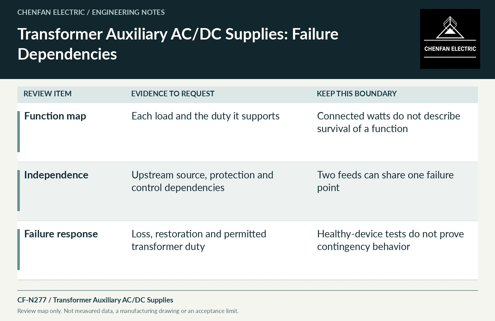
| Function map | Each load and the duty it supports | Connected watts do not describe survival of a function |
| Independence | Upstream source, protection and control dependencies | Two feeds can share one failure point |
| Failure response | Loss, restoration and permitted transformer duty | Healthy-device tests do not prove contingency behavior |
References and scope
- IEC 60076-1:2011 — Power transformers: GeneralPublic standard abstract · General transformer scope, interfaces and controlled equipment specification.
- IEEE C57.91-2025 — Loading Mineral-Oil-Immersed Transformers and Step-Voltage RegulatorsPublic standard abstract · Mineral-oil loading, thermal duty and loading beyond nameplate; do not transfer the scope automatically to ester or dry-type equipment.
- IEEE C57.165-2024 — Temperature Monitoring of Liquid-Immersed TransformersPublic standard abstract · Temperature-monitoring methods for liquid-immersed transformers and their measurement/model boundaries.