

Shunt saturation depends on collected flux and effective steel area normal to that flux. Account for coating, gaps and direction to compare packet thicknesses on their actual magnetic section. [1]
Use the correct section
For a defined flux path, estimate mean flux density as collected magnetic flux divided by effective steel area normal to that path. If the section is formed by packet width and stack thickness, identify the applicable stacking factor and how it was established. Do not apply that area to a different flux direction or to a transfer region crossing the laminations.
For an illustrative gross section of 0.0010 m², a stacking factor of 0.94 gives an effective section of 0.00094 m². A fictional flux of 0.0010 Wb then gives a mean density of approximately 1.064 T, rather than the 1.000 T obtained with gross area. This arithmetic supplies no saturation criterion for the material.
Retain the local peak map
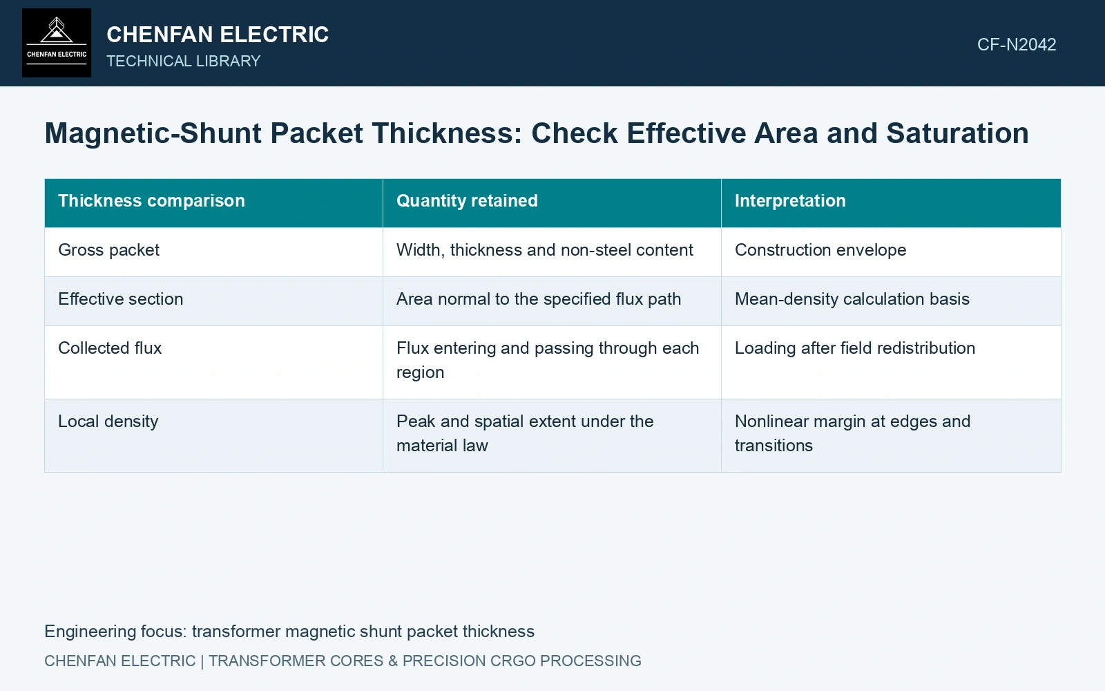
| Thickness comparison | Quantity retained | Interpretation |
|---|---|---|
| Gross packet | Width, thickness and non-steel content | Construction envelope |
| Effective section | Area normal to the specified flux path | Mean-density calculation basis |
| Collected flux | Flux entering and passing through each region | Loading after field redistribution |
| Local density | Peak and spatial extent under the material law | Nonlinear margin at edges and transitions |
The published multi-step shield study explicitly accounts for enhanced flux entering outermost stacks and calculates a nonlinear shield response. It demonstrates why the average packet density cannot stand in for the edge result. Its comparison is with a 3D field model, not a universal saturation guarantee. [1]
Recompute the loading after a thickness change
A thicker packet can collect a different amount of flux because it changes the surrounding magnetic circuit. Holding flux constant while increasing area is useful for an initial sensitivity calculation, but the final comparison must update the coupled field. Inspect neighbouring packets and the tank as well as the modified section. [2]
Use a representative directional magnetization curve for the relevant material and processing state. Define the engineering limit and margin from that curve and the design requirement; a generic “saturation density” cannot replace the field required near the operating point.
At the stated assumed flux, effective area 0.0010 × 0.94 = 0.00094 m² gives mean B = 1.0638 T. An assumed 30% outer-entry enhancement gives 1.3830 T. If directional material data for this exercise cover only through an assumed 1.30 T, the average is covered but the outer screen is not. Hold this thickness candidate for a resolved directional field assessment. The multiplier and data endpoint are fictional inputs, not measured enhancement or a saturation limit. Increasing gross area alone cannot settle the outer packet’s duty.
Compare effective area, collected flux and local peaks on one basis. Select the thickness whose governing region retains the justified magnetic margin under the specified cases.
References
- Z. Jurković, B. Jurišić and T. Župan, Multi-Step Approach for Fast Calculation of Magnetic Field in Transformer Tank Shields, Energies 17, 1378, 2024. DOI: 10.3390/en17061378.
- I. A. Hernandez-Robles et al., Analysing and Computing the Impact of Geometric Asymmetric Coils on Transformer Stray Losses, Applied System Innovation 7, 26, 2024. DOI: 10.3390/asi7020026.