

A magnetic-shunt overlap transfers leakage flux through its own local field and material orientation. Assess that interface and adjacent metal to choose the overlap for the actual shunt construction.
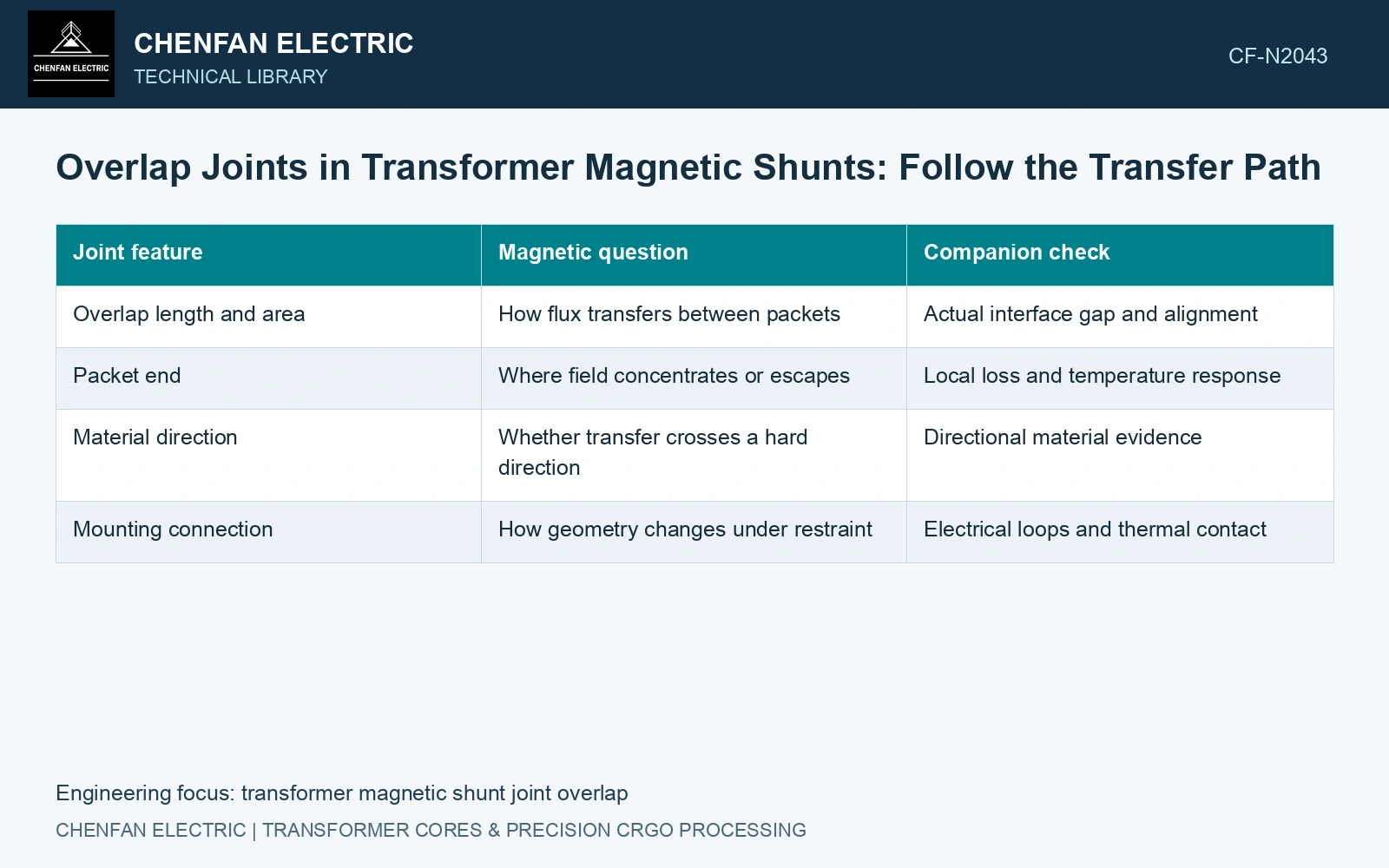
Draw the interface paths separately
Map where flux leaves one packet, crosses a gap/coating interface and enters the next. Record rolling directions, overlap area and actual separation. A nominal mechanical overlap is not continuous magnetic steel; B = Φ/A only screens the defined transfer section. [1]
On the same drawing, identify possible electrical connections through damaged coating, fasteners or supports. Magnetic coupling and electrical continuity are different properties. An interface can transfer useful flux while remaining electrically insulated; it can also create an unwanted current path without providing the intended magnetic geometry.
| Joint feature | Magnetic question | Companion check |
|---|---|---|
| Overlap length and area | How flux transfers between packets | Actual interface gap and alignment |
| Packet end | Where field concentrates or escapes | Local loss and temperature response |
| Material direction | Whether transfer crosses a hard direction | Directional material evidence |
| Mounting connection | How geometry changes under restraint | Electrical loops and thermal contact |
Compare geometry under the same source
Keep the winding arrangement and excitation fixed when comparing overlaps. Change the joint parameter deliberately and recompute the coupled field. Inspect both packets, the adjacent tank and exposed joint ends. A reduced field in one packet may mean that more flux has escaped into the neighbouring tank region.
Check mesh resolution and interface representation where the gap is small. A model that merges the packets into one continuous solid cannot assess the interface it has removed. A model with an exaggerated gap can overstate its reluctance.
Connect local field with local heat
Evaluate the relevant loss mechanisms in the joint and surrounding metal using a suitable material and current-path model. Transfer the spatial losses into the thermal assessment with the actual oil access and mounting conduction. A whole-packet average loss can conceal concentrated heating at an end or fastener.
The shield-field study resolves nonuniform magnetic loading in the shunt assembly. Apply that spatial discipline to a proposed overlap, then validate its transfer path directly instead of importing a main-core joint result. [2]
Assume a joint transfers 0.0010 Wb through effective overlap section 0.0010 m²: mean B = 1.0 T [1]. A positional shift halving the section to 0.00050 m² gives a 2.0 T mean screen. Assume directional material data in this exercise cover only through 1.6 T; the shifted joint is outside that range, while the first mean lies within it. Hold the shifted construction and obtain local directional field/nonlinear data before acceptance. This is a model-coverage decision, not a saturation prediction; fringing and end peaks still require resolution [2].
Qualify the measured overlap construction against local magnetic and thermal outcomes. Retain the flux-transfer geometry and neighbouring-metal response with the selected dimension.
References
- U.S. Department of Energy, DOE-HDBK-1011/4-92, Electrical Science, Volume 4, 1992.
- Z. Jurković, B. Jurišić and T. Župan, Multi-Step Approach for Fast Calculation of Magnetic Field in Transformer Tank Shields, Energies 17, 1378, 2024. DOI: 10.3390/en17061378.