


Transformer Core Engineering Notes · CF-N214
The lead exit is where a conductor leaves a relatively regular winding geometry and enters a more complicated insulation space. Its route, bends and supports can become limiting even when the main winding clearances are generous. Review the complete transition to the next connection, not merely the point labelled “lead” on a section drawing.
Trace the conductor through every nearby boundary
Identify the winding end, insulation cylinder, yoke, clamp and other leads around the exit. Record the relevant potentials and minimum spaces in the assembled condition. A lead can move closer to a grounded structure outside the main winding section, so a two-dimensional radial drawing may miss the limiting region. Where the geometry is three-dimensional, the review should include sufficient views or modelling to explain the actual closest approaches.
Bends and terminations need controlled shapes
The conductor bend, insulation wrapping and termination edge together determine the local geometry. A nominal bend radius is not enough if the insulation arrangement at the transition is undefined. Ask how the supplier controls conductor forming, overlap and the support location that holds the lead in place. The approved design should distinguish a deliberate grading feature from an incidental metal edge or fastening detail introduced during assembly.
Support is also an insulation control
Mechanical restraint limits displacement during handling and electrical fault duty. An unsupported or differently supported lead may no longer maintain the spacing assumed in the insulation model. Conversely, a support can introduce a new surface path or obstruct cooling. Evaluate its material, location and fastening as part of the lead design. Inspection should confirm the completed route and clearances, not just the continuity of the conductor between its labelled terminals.
Manage late routing changes
Lead routes often change to resolve a practical assembly conflict. Before accepting that change, compare the new path against electrical clearances, local field treatment, support loads and accessibility. Confirm whether previous dielectric evidence still represents the altered region. A photograph of the completed lead is useful for traceability but does not prove its withstand capability. Record the accepted arrangement in a revised drawing so subsequent units do not inherit an undocumented workaround.
| Review item | Evidence to request | Boundary to preserve |
|---|---|---|
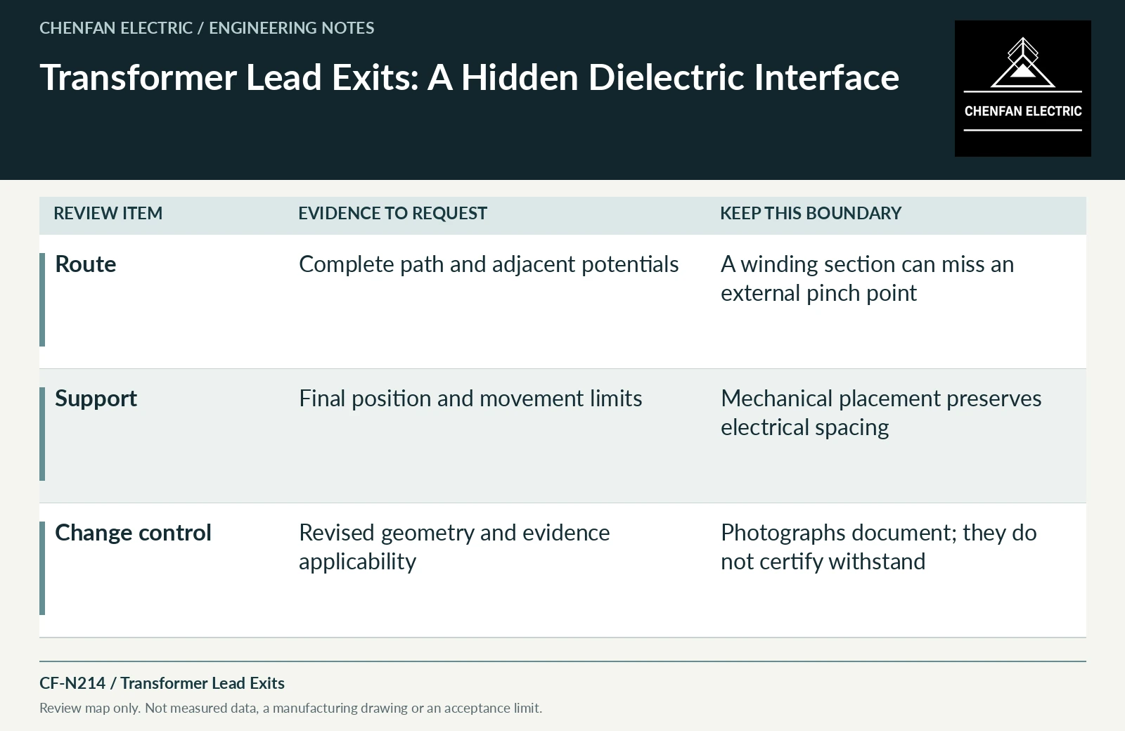
| Route | Complete path and adjacent potentials | A winding section can miss an external pinch point |
| Support | Final position and movement limits | Mechanical placement preserves electrical spacing |
| Change control | Revised geometry and evidence applicability | Photographs document; they do not certify withstand |
References and scope
- IEC 60076-3:2013+AMD1:2018 CSV — Insulation levels and dielectric testsPublic standard abstract · Insulation levels, dielectric testing and external clearances; the article does not reproduce test values or design distances.
- Bushing Maintenance (FIST 3-2)Historical technical manual · Bushing components, connection and maintenance interfaces.
- IEC 60076-5:2006 — Ability to withstand short circuitPublic standard abstract · Thermal and dynamic short-circuit capability; calculation and verification apply to the actual design.