


Transformer Core Engineering Notes · CF-N213
An electrostatic shield is a deliberately positioned conductive feature with a defined electrical connection. It may be used to influence capacitive coupling or local electric-field distribution. It is not a universal cure for harmonics, noise or insulation problems. Specify the intended function before adding a shield to a transformer drawing.
Separate coupling control from magnetic shielding
A conductive screen between windings can alter capacitance and the path of displacement current. That is different from controlling leakage magnetic flux with a magnetic shield. Ask what quantity the design is intended to change and under what frequency or transient conditions. A requirement such as “install an electrostatic shield” is incomplete without a circuit description and performance basis. Do not assume that the presence of a screen establishes a specified attenuation over every frequency.
Define potential and connection explicitly
The shield’s intended potential, bonding point and lead route belong on the controlled design documents. A floating screen behaves differently from a deliberately connected screen. The connection itself needs suitable insulation, mechanical support and current-duty consideration. Avoid informal field changes to grounding arrangements: they can alter coupling, create unintended current paths or invalidate the insulation review. Verify the delivered connection against the approved circuit rather than relying on a descriptive label.
Avoid a conducting loop around core flux
A conducting loop linked by alternating core flux can behave as a shorted turn. Shield design must therefore consider continuity, overlap, gaps and insulation so that its intended electrostatic role does not create an unintended electromagnetic circuit. This is a geometry-specific design issue, not a universal instruction to cut or disconnect every metal screen. The OEM must define the construction, including how the ends and any overlap are insulated and supported.
Check side effects before claiming a benefit
Adding a shield changes the winding-to-winding arrangement and may affect local electric stress, cooling space or the finished coil envelope. Compare these effects with the intended coupling benefit. Any performance test should state the source, load, connection and measurement conditions. Without those details, two attenuation figures may not describe the same problem. Maintain a drawing-linked acceptance record and recheck the design if the shield position, lead route or surrounding insulation changes.
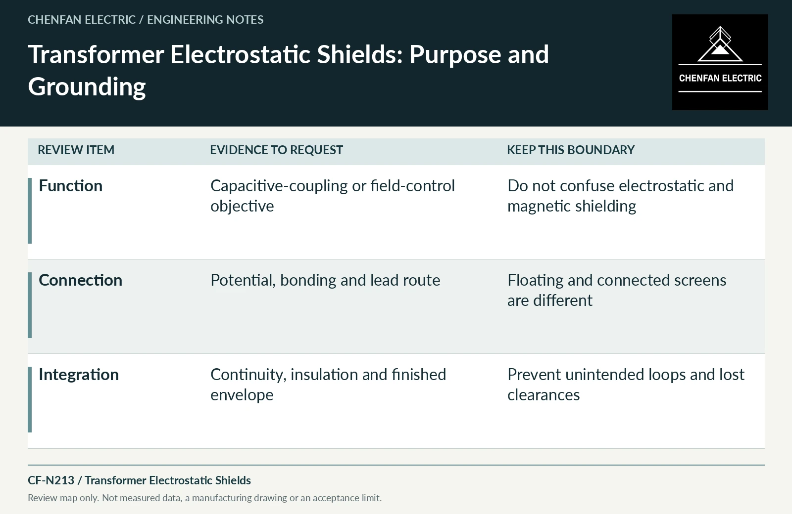
| Review item | Evidence to request | Boundary to preserve |
|---|---|---|
| Function | Capacitive-coupling or field-control objective | Do not confuse electrostatic and magnetic shielding |
| Connection | Potential, bonding and lead route | Floating and connected screens are different |
| Integration | Continuity, insulation and finished envelope | Prevent unintended loops and lost clearances |
References and scope
- IEC 60076-3:2013+AMD1:2018 CSV — Insulation levels and dielectric testsPublic standard abstract · Insulation levels, dielectric testing and external clearances; the article does not reproduce test values or design distances.
- IEC 60076-5:2006 — Ability to withstand short circuitPublic standard abstract · Thermal and dynamic short-circuit capability; calculation and verification apply to the actual design.