


Transformer Core Engineering Notes · CF-N283
A lifting lug, jacking pad and skidding surface perform different mechanical functions. Their appearance or proximity does not make them interchangeable. The OEM must identify the approved points and conditions for each handling operation, while the qualified contractor develops a plan for the actual mass, configuration, route and equipment.
Identify each point by its intended function
The handling drawing should distinguish whole-unit lifting points from cover or accessory lifting points, and show jacking and skidding interfaces separately. A point intended for a removable component may be incapable of supporting the complete transformer. Do not infer capacity from plate thickness or a visible hole. Use the OEM’s documented function, permissible loading and applicable configuration.
Follow the load path into the structure
A local contact transfers force into the tank, base or frame through a designed path. Changing the contact location can load a panel or weld differently from the approved arrangement. Temporary supports also need a defined bearing interface. The contractor should resolve these details with the OEM rather than improvising a new support under a convenient flat surface.
Assess the operation as a sequence
Moving from transport support to jacks, temporary blocks or rails changes how the load is carried. Each stage requires the qualified plan’s stability and capacity assessment. Uneven foundations or a constrained route can affect the sequence. This article does not provide lifting, jacking or rigging instructions; those operations must use approved equipment, competent personnel and the applicable site safety process.
Control documentation and physical condition
Verify the drawing revision and handling state before work begins. Inspect the designated interfaces as required by the approved plan and resolve damage or missing identification with the OEM. A later modification to the base or accessories may require revised instructions. The final handover should retain the approved handling documents for future relocation or replacement rather than relying on photographs of the original installation.
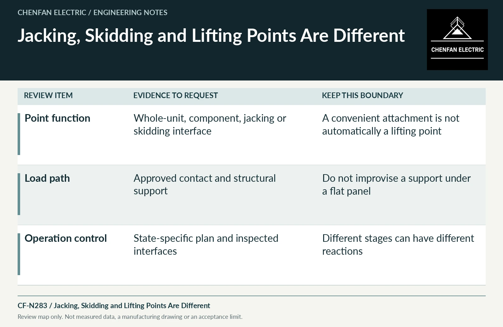
| Review item | Evidence to request | Boundary to preserve |
|---|---|---|
| Point function | Whole-unit, component, jacking or skidding interface | A convenient attachment is not automatically a lifting point |
| Load path | Approved contact and structural support | Do not improvise a support under a flat panel |
| Operation control | State-specific plan and inspected interfaces | Different stages can have different reactions |
References and scope
- IEC 60076-1:2011 — Power transformers: GeneralPublic standard abstract · General transformer scope, interfaces and controlled equipment specification.
- Dry-Type Transformers 1000 Volts and Below — Instruction Bulletin 43006-850-01Manual listing / metadata only · Example of why handling and installation instructions must match the actual product and voltage range.