

A transformer feeder may include old paper-insulated cable, a replacement XLPE section and several transition joints. Electrically it is one circuit. Diagnostically it contains different material populations and interfaces. The assessment should preserve those differences rather than treating the entire length as a homogeneous cable. [1]
Start with a section map. Identify insulation construction, lengths, joint types and replacement history. Mark uncertain records. An assessment based on an assumed all-XLPE route can be misleading even when the test instrument is functioning correctly.
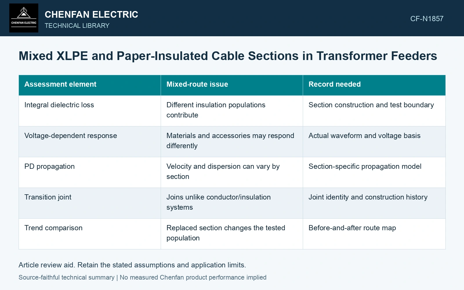
Assign each observation to its boundary
A dielectric-loss measurement responds to the connected tested circuit. A localized PD signal adds another kind of information, while its location depends on signal propagation through the route. These observations should be interpreted with the section map beside them.
| Assessment element | Mixed-route issue | Record needed |
|---|---|---|
| Integral dielectric loss | Different insulation populations contribute | Section construction and test boundary |
| Voltage-dependent response | Materials and accessories may respond differently | Actual waveform and voltage basis |
| PD propagation | Velocity and dispersion can vary by section | Section-specific propagation model |
| Transition joint | Joins unlike conductor/insulation systems | Joint identity and construction history |
| Trend comparison | Replaced section changes the tested population | Before-and-after route map |
Avoid a length-only dielectric average
The contribution of a section to the measured response depends on its electrical properties and the test circuit, not solely on its fraction of route length. A simple average of two catalog tan-delta values is not automatically the response of their connected cable system.
Likewise, one propagation speed can introduce a location error. In a segmented path, travel time is accumulated through each section. A transition boundary can also produce reflections that need to be separated from source pulses.
Read the method’s limits before the condition label
Do not assign one material’s acceptance interpretation to another section without a justified method. A favorable circuit-level result also cannot certify every transition joint. A bulk insulation concern and a local interface concern remain separate questions.
Pulse-location methods need the original/reflected path and calibrated propagation speed. Shafiq and co-authors show that calculated dielectric-based speed can differ from a measured cable speed; retain the calibration evidence when a mixed route is reconstructed. [2]
Locate a pulse through mixed sections
Assumptions: a known one-way signal path contains 300 m of cable at 160 m/μs and 200 m at 200 m/μs. Travel time is 300/160 + 200/200 = 2.875 μs. Applying 200 m/μs to the full time gives 575 m instead of 500 m, an error of 75 m. If surveyed candidate components are at 500 m and 575 m, the uniform-speed estimate would assign the wrong component. Retain the 500 m candidate under the segmented model and confirm its timing uncertainty before intrusive work. For a reflected PD pair, first convert the actual extra travel path into the appropriate source coordinate. [2]
References
- IEEE, IEEE 400.2-2024, IEEE Guide for Field Testing of Shielded Power Cable Systems Using Very Low Frequency (VLF) (less than 1 Hz).
- M. Shafiq, I. Kiitam, P. Taklaja, L. Kütt, K. Kauhaniemi and I. Palu, Identification and Location of PD Defects in Medium Voltage Underground Power Cables Using High Frequency Current Transformer, IEEE Access 7, 2019. DOI: 10.1109/ACCESS.2019.2930704.