

A larger transformer does not automatically justify higher current in its existing feeder cable. The cable may have thermal margin, or it may already be limited by a short duct section, a joint or adverse ground conditions. The cross-section printed on a record cannot settle the installed rating. [1]
The uprating case should name the duty being proposed. A new continuous rating, a daily peak pattern and temporary emergency loading require different thermal histories. Do not combine their most favorable results into one unrestricted capacity claim.
Establish what is installed
Verify cable construction, route, lengths, bonding, joints, terminations and relevant installation sections. Resolve differences between legacy drawings and site evidence. A catalog model selected by conductor size alone may assign the wrong insulation, metallic layers or loss behavior.
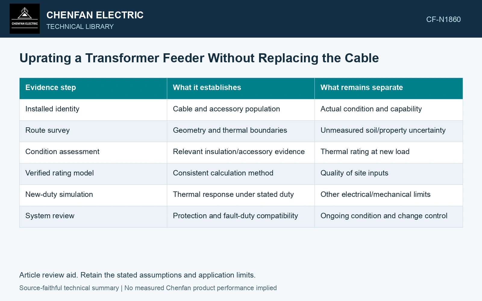
| Evidence step | What it establishes | What remains separate |
|---|---|---|
| Installed identity | Cable and accessory population | Actual condition and capability |
| Route survey | Geometry and thermal boundaries | Unmeasured soil/property uncertainty |
| Condition assessment | Relevant insulation/accessory evidence | Thermal rating at new load |
| Verified rating model | Consistent calculation method | Quality of site inputs |
| New-duty simulation | Thermal response under stated duty | Other electrical/mechanical limits |
| System review | Protection and fault-duty compatibility | Ongoing condition and change control |
Build the thermal case around the limiting section
Include conductor, dielectric and metallic-layer losses as applicable. Represent soil, backfill, ducts, crossings and neighboring circuits. Use credible adverse properties and ambient conditions rather than the most favorable observation collected during a survey.
Review the other duties the higher current changes
Higher load affects joints and terminations as well as the cable body. Check their accepted continuous and transient duty. Changes in transformer or network impedance can also affect fault currents and protection coordination. These are separate assessments; a favorable conductor-temperature result does not cover them.
Retain insulation-condition evidence with its method limits. Condition testing can identify relevant concerns, but it does not calculate ampacity. Likewise, a thermal model cannot establish that an aged accessory is free of a localized defect.
For a simplified steady thermal node, temperature rise equals heat input multiplied by effective thermal resistance. A cable route needs the losses and heat paths of its limiting section, rather than a transformer nameplate-based current allowance. [2]
Screen the increased conductor loss
Assumptions for a preliminary limiting-section screen: 400 A produces a conductor temperature of 70 °C in 25 °C surroundings; conductor AC resistance and effective thermal resistance remain constant, and other losses are neglected. The proposed 500 A raises conductor loss by (500/400)² = 1.5625, or 56.25%. The same thermal node predicts T = 25 + (70 − 25)×1.5625 = 95.31 °C. Against an assumed project conductor limit of 90 °C, the proposal fails by 5.31 K. This model gives Imax = 400√[(90 − 25)/(70 − 25)] = 480.74 A. Hold the 500 A uprating until a complete route/accessory assessment demonstrates adequate capacity; use temperature-dependent losses for that approval calculation. [1][2]
References
- IEC, IEC 60287-1-1:2023, Electric cables — Calculation of the current rating — Part 1-1: Current rating equations (100 % load factor) and calculation of losses — General.
- U.S. Department of Energy, DOE-HDBK-1012/2-92, Thermodynamics, Heat Transfer, and Fluid Flow, Volume 2, 1992.