

A cable detour can preserve both end terminals while changing the electrical circuit between them. Added length, a new construction or a revised bonding arrangement can affect fault current and the quantities used by protection. The original settings should not be carried forward solely because the transformer and relay names remain the same. [1]
The review begins with the as-built route change. Identify which electrical parameters changed and where they enter the protection model. A civil route sketch is useful evidence, but it is not the complete network model.
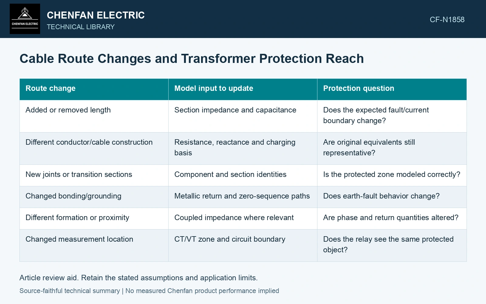
Translate physical changes into electrical inputs
| Route change | Model input to update | Protection question |
|---|---|---|
| Added or removed length | Section impedance and capacitance | Does the expected fault/current boundary change? |
| Different conductor/cable construction | Resistance, reactance and charging basis | Are original equivalents still representative? |
| New joints or transition sections | Component and section identities | Is the protected zone modeled correctly? |
| Changed bonding/grounding | Metallic return and zero-sequence paths | Does earth-fault behavior change? |
| Different formation or proximity | Coupled impedance where relevant | Are phase and return quantities altered? |
| Changed measurement location | CT/VT zone and circuit boundary | Does the relay see the same protected object? |
Recalculate the affected circuit
For a uniform section with constant series impedance per length z in ohms per metre, its series impedance is zL, where L is length in metres. A segmented route requires the relevant section contributions and a consistent electrical reference. This simple relation explains a length effect; it is not a substitute for a cable’s phase or sequence model.
Earth-fault behavior can be especially sensitive to return paths and grounding. The physical cable length does not establish zero-sequence impedance on its own. Preserve how screens, grounds and parallel paths were represented in the accepted study.
Compare limiting cases after the change
Review the credible minimum and maximum source conditions, relevant fault locations and system configurations. A modified route can alter fault sensitivity at a remote location while changing another duty near the source. The protection review should examine both rather than report only one favorable current.
A changed route can also change connected phase-to-earth capacitance and the parallel ground-current path seen by feeder protection. [2] Update that contribution separately from the new series-impedance section and the metallic return model.
Put the route change into ohms
Assume a feeder is extended by 300 m with positive-sequence impedance 0.20 + j0.10 Ω/km. The added impedance is 0.060 + j0.030 Ω. Insert this value in the actual fault model, including its separate return-path model, before reviewing protection reach. Thermal ampacity evidence does not establish relay sensitivity.
References
- D. De Ronde, R. VanHatten and A. Wade, Loss of Effective System Grounding — Best Practices, Protection Challenges, and Solutions, Schweitzer Engineering Laboratories, 2015.
- T. Novak, J. Basar, J. Sottile and J. L. Kohler, The Effects of Cable Capacitance on Longwall Power Systems, IEEE Transactions on Industry Applications 40(5), 2004; DOI: 10.1109/TIA.2004.834025.