

Disconnecting a dielectric excitation does not prove that every insulation region has relaxed. Dielectric absorption can produce voltage recovery after a terminal condition changes. Safe handling and a reproducible initial state must follow the approved equipment and instrument procedures. [1]
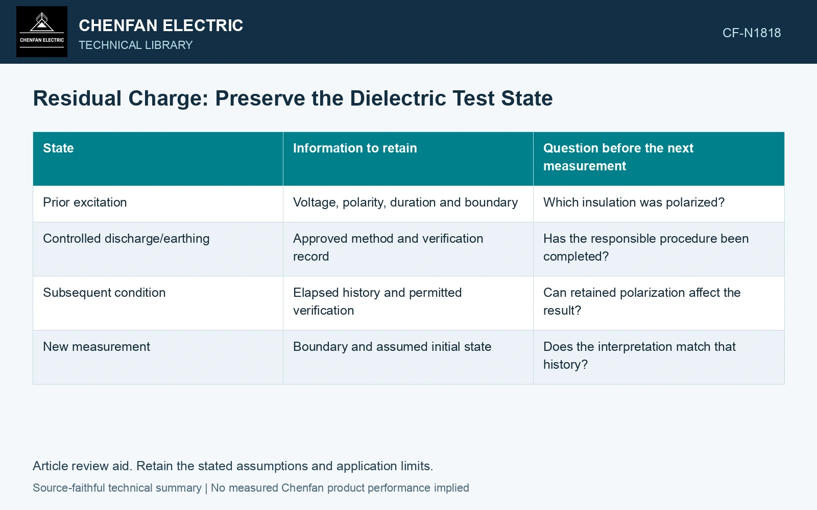
Record the transition, not only the next test name
| State | Information to retain | Question before the next measurement |
|---|---|---|
| Prior excitation | Voltage, polarity, duration and boundary | Which insulation was polarized? |
| Controlled discharge/earthing | Approved method and verification record | Has the responsible procedure been completed? |
| Subsequent condition | Elapsed history and permitted verification | Can retained polarization affect the result? |
| New measurement | Boundary and assumed initial state | Does the interpretation match that history? |
Keep safety verification and model relaxation separate
An approved discharge verification serves a safety purpose. It does not necessarily establish the ideal relaxed state assumed by a mathematical PDC model. Slow polarization may remain relevant to interpretation even after the approved handling procedure is complete.
Neither a universal waiting time nor a simple capacitor calculation captures every material and test history. The actual instructions determine safe transitions. Analytical assumptions must additionally account for charging duration, discharge history and any observed recovery behavior.
The extended Debye representation used by Raxsa and co-authors places series RC relaxation branches in parallel with geometric capacitance. Those branches retain state beyond the instant terminal capacitance is discharged. [2]
Model recovery after an idealized fast terminal discharge
Assumptions for an isolated two-capacitor model: C₀ = 10 nF is parallel to a series branch R₁ = 100 MΩ, C₁ = 40 nF, with negligible parallel DC leakage. Long prior excitation charges both capacitors to 500 V. An ideal instantaneous terminal short sets C₀ to 0 V while C₁ remains at 500 V; after removal, charge redistributes through R₁. The final terminal voltage is 500C₁/(C₀ + C₁) = 400 V, with recovery time constant R₁C₀C₁/(C₀ + C₁) = 0.8 s. At 1 s, the model gives 400(1 − e⁻¹/⁰·⁸) = 285.4 V despite the initially zero terminal voltage. Record the actual discharge/history state before fitting the next trace. This ideal model specifies no safe waiting time or handling procedure. [2]
References
- IEEE, IEEE C57.161-2018, IEEE Guide for Dielectric Frequency Response Test.
- J. Raxsa, P. Nimsanong, T. Mai-Eiam and P. Yutthagowith, Determination of Dielectric Models Based on Effective Multi-Exponential Fittings, Energies 16, 4615, 2023. DOI: 10.3390/en16124615.