

A transformerwood pressure beam needs its veneer layup tied to the bending and test directions. Define grain, stacking plane and part axes on one drawing to select the construction for the actual duty. [1]
Give those directions separate names on the drawing. Identify the beam length, the veneer grain directions, the layer-plane normal and the installed loading direction. A datasheet symbol for a test perpendicular to the layers does not identify every grain direction within them.
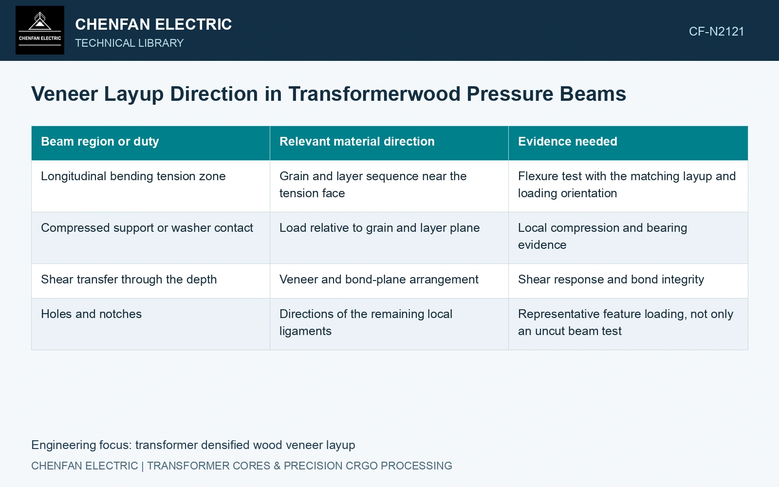
Map the beam loads to the layup
| Beam region or duty | Relevant material direction | Evidence needed |
|---|---|---|
| Longitudinal bending tension zone | Grain and layer sequence near the tension face | Flexure test with the matching layup and loading orientation |
| Compressed support or washer contact | Load relative to grain and layer plane | Local compression and bearing evidence |
| Shear transfer through the depth | Veneer and bond-plane arrangement | Shear response and bond integrity |
| Holes and notches | Directions of the remaining local ligaments | Representative feature loading, not only an uncut beam test |
One manufacturer’s parallel-stack grade gives flexural data with an explicit condition on longitudinal layers in the tension zone. That condition belongs with the data. Reversing a beam or machining away some of those layers can change whether the published test arrangement still represents it.
Layer placement matters as well as the average
In a simplified, linear, perfectly bonded beam model, bending stiffness can be written as a sum of layer contributions: EI = Σ Eᵢ(Iᵢ + Aᵢyᵢ²), about the appropriate elastic neutral axis. Layers farther from that axis have a larger lever-arm contribution.
This expression illustrates why a through-thickness average modulus cannot generally describe every stacking sequence. It is not a complete orthotropic laminate model: directional shear, coupling, bond behaviour and local contacts may need separate treatment.
Parallel-grain and crossed-grain stacks can therefore have different tradeoffs between longitudinal bending, transverse behaviour and dimensional stability. Choose the manufacturer’s exact construction and test directions, rather than treating the same density as proof of equivalent beam performance.
Verify the veneer arrangement on a representative stock section and preserve it during machining. Record which face becomes the tension face and how the beam is installed. Where the load can reverse, qualification must account for both relevant faces.
Link the purchased grade to the layup drawing and beam-test orientation. Preserve that construction identity when comparing or substituting geometrically identical blocks.
Compare identical layer counts in two stacking orders
Keep the grade and flexural test orientation explicit [2]; the named data sheet also qualifies its tension-zone layer arrangement [1]. For a separate planning model, assume sixteen perfectly bonded 1 mm layers, width 100 mm, symmetric about mid-depth. Eight layers have hypothetical axial E = 10 GPa and eight E = 3 GPa, with no material values inferred from that catalogue.
Arrangement A puts four high-E layers at each outer face and eight low-E layers in the centre; B reverses those positions. Both arithmetic average moduli are 6.5 GPa. The total and central-half second moments are 34,133.3 and 4,266.7 mm⁴. Summing layer EI gives 311.467×10⁶ N·mm² for A and 132.267×10⁶ N·mm² for B.
For an assumed simply supported 200 mm span and central 1 kN load, neglecting shear, deflections PL³/(48EI) are 0.5351 mm and 1.2601 mm. Against an assumed 1.0 mm bending allocation, only A passes. Preserve layer placement, then verify actual shear, bond, contact and oil-conditioned performance; equal layer counts and average modulus do not establish equivalent beams.
References
- Röchling Industrial, Lignostone L I/2-E3-HQ (P2R), Technical Data Sheet, version 2.0, released 20 September 2023.
- IEC, IEC 61061-2:1992, Specification for non-impregnated, densified laminated wood for electrical purposes — Part 2: Methods of test.