

The word pressure can obscure the mechanical state at a transformer core joint. A normal contact force and an in-plane force resisting sliding act differently. If the material data describe one state and the assembly creates the other, the model may apply a magnetic correction in the wrong direction.
Resolve contact forces into the sheet’s coordinate system. Identify rolling direction, transverse direction and the normal to the lamination. The resulting local stress depends on contact geometry, load transfer and restraint; dividing an external clamp force by a convenient area may not describe it.
A pure-shear illustration
Consider an idealized plane stress state with zero normal components in r and t, and in-plane shear stress tau. The symmetric stress matrix has diagonal terms zero and off-diagonal terms tau. Its principal stresses are +tau and −tau, directed at 45 degrees to the original axes for this idealization.
This example shows why shear is not equivalent to compression of the same nominal magnitude. It creates simultaneous principal tension and compression in directions that may not coincide with the steel’s rolling direction. A real joint generally includes additional normal stresses and nonuniform contact.
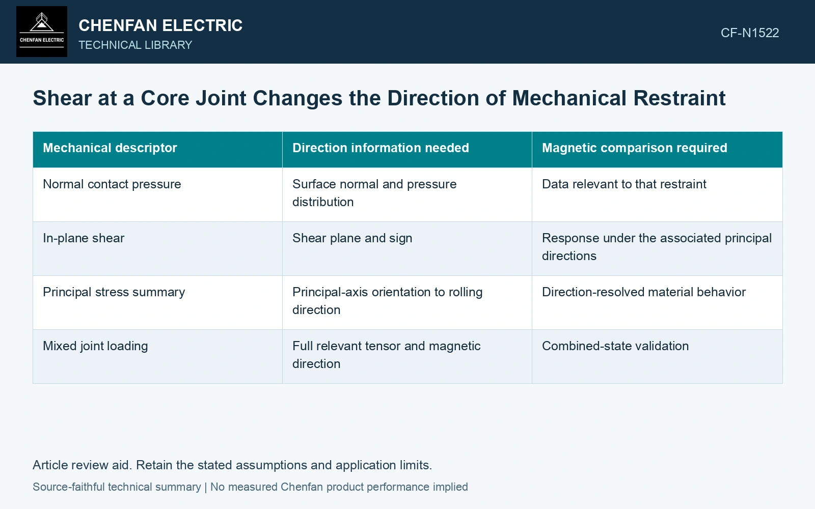
| Mechanical descriptor | Direction information needed | Magnetic comparison required |
|---|---|---|
| Normal contact pressure | Surface normal and pressure distribution | Data relevant to that restraint |
| In-plane shear | Shear plane and sign | Response under the associated principal directions |
| Principal stress summary | Principal-axis orientation to rolling direction | Direction-resolved material behavior |
| Mixed joint loading | Full relevant tensor and magnetic direction | Combined-state validation |
The tensor description should use the same coordinate convention as the magnetic calculation. A sign or axis change can alter the interpreted coupling without changing the printed maximum stress.
Connect the mechanical model to an observable region
Identify where the joint transfers sliding load and where contact changes or terminates. Verify those regions with representative mechanical observations where practical. A model whose contact assumption prevents all slip may predict a different local stress from one with measured movement.
In magnetic testing, define the direction of magnetization relative to both rolling direction and principal stress. The joint’s local magnetic field may rotate, so a rolling-direction material curve alone can be insufficient even before the shear effect is added.
Treat the missing state as a verification question
If only normal compression data exist, state that limitation rather than transforming them into a shear curve by a scalar multiplier. A useful trial compares selected loading orientations while controlling excitation, magnetic history and temperature. Repeat the unloaded state to examine recovery.
Where a coupled model is used, perturb the shear component and orientation independently to identify which predictions are sensitive to the missing data. This can prioritize the trial region and response to measure. The result should explain how a specific joint’s load path interacts with anisotropic magnetic behavior, instead of attaching an unsupported general loss penalty to the word shear.
Technical references
- Materials / MDPI. Magnetostrictive Properties of the Grain-Oriented Silicon Steel Sheet under DC-Biased and Multisinusoidal Magnetizations.
- NIST. NCAL: Diffraction Stress Measurement Under Applied Load.