

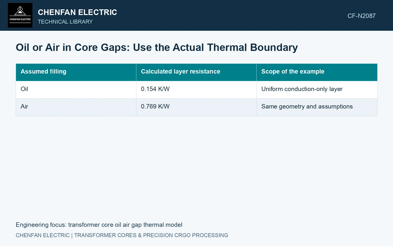
The same oil-filled fraction can produce different core-gap temperatures when the oil and gas occupy different positions. Determine whether the remaining gas interrupts the heat path or sits beside a wetted path before assigning an equivalent conductivity.
Identify the heat path before assigning a gap material
For a uniform stationary layer, conduction resistance is R = d/(kA). Resistances add along a series heat path; conductances add for paths beside one another. [1] Contact spots, wetting and gas-pocket geometry therefore matter alongside the volume of trapped gas. A liquid-filled tank does not prove that an internal cavity is wetted.
Keep this local gap model separate from the laminated steel and its spreading resistance. Published core-temperature modelling uses directional thermal properties and construction-specific boundaries; a single gap coefficient cannot replace those inputs. [2]
Compare equal filling fractions with different arrangements
Catalogue input: 23ZH90 has nominal gauge 0.23 mm, density 7,650 kg/m³ and maximum strip loss 0.90 W/kg at 1.7 T, 50 Hz. [3] Assumptions for a local screen: 100 laminations each have 0.10 m² area; their entire strip-loss budget crosses one stationary 0.20 mm gap of area 0.010 m². Ignore other heat paths. At an assumed 40 °C boundary, use assumed constant conductivities of 0.13 W/(m·K) for oil and 0.026 W/(m·K) for gas. Specify actual fluid properties at the operating temperature before applying the screen to a product.
The steel mass is 100 × 0.10 × 0.00023 × 7,650 = 17.595 kg, giving a strip-source ceiling of 15.8355 W. This does not include joint or clamp losses. The gap-only rise is Q × R.
| Assumed gap state | Calculated resistance | Calculated gap rise |
|---|---|---|
| Entirely oil | 0.15385 K/W | 2.44 K |
| Entirely gas | 0.76923 K/W | 12.18 K |
| 50% oil, equal side-by-side areas | 0.25641 K/W | 4.06 K |
| 50% oil, equal layers along the heat path | 0.46154 K/W | 7.31 K |
For the side-by-side case, R = d/[A(0.5koil + 0.5kgas)]. For the series case, R = 0.5d/(koilA) + 0.5d/(kgasA). Both contain the same oil volume, but the series arrangement gives an 80% larger rise.
Resolve the geometry that changes the decision
Assume the design allocates a maximum 5 K rise to this gap alone. The parallel arrangement passes this limited screen; the series arrangement fails. A record stating “50% filled” cannot decide which result applies. Establish the actual wetted footprint and gas-layer continuity, or retain the adverse arrangement in the calculation.
During core assembly, control gap thickness, contact pressure, support footprint and filling access. Replace the strip-loss budget with measured assembled-core loss and its spatial distribution before assessing a packet hot spot. Include steel spreading, neighbouring heat sources and oil circulation in the final thermal model.
References
- U.S. Department of Energy, DOE-HDBK-1012/2-92, Thermodynamics, Heat Transfer, and Fluid Flow, Volume 2, 1992.
- Z. Chen, Z. He and S. Wang, Transformer Iron Core Temperature Field Calculation Based on Finite Element Analysis, Energies 18, 6537, 2025. DOI: 10.3390/en18246537.
- Nippon Steel Corporation, Grain-Oriented Electrical Steel Sheets, catalogue D004je, April 2020, specification and typical-property tables.