

Spacer positions determine core-duct supply, sheltered pockets and conductive heat paths. Compare the connected channel layout to target the spacer or interface that controls local cooling. [1]
Compare spacer positions on the heat and flow map, keeping their structural function explicit. Removing a spacer from a thermal model without replacing its support duty creates an unrealizable alternative.
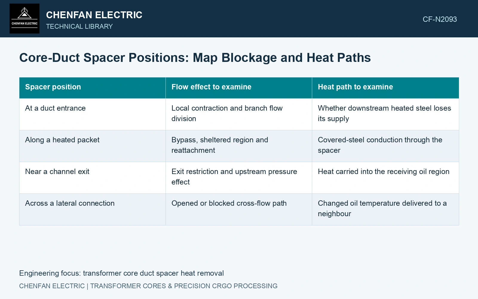
Locate restrictions relative to the heat source
| Spacer position | Flow effect to examine | Heat path to examine |
|---|---|---|
| At a duct entrance | Local contraction and branch flow division | Whether downstream heated steel loses its supply |
| Along a heated packet | Bypass, sheltered region and reattachment | Covered-steel conduction through the spacer |
| Near a channel exit | Exit restriction and upstream pressure effect | Heat carried into the receiving oil region |
| Across a lateral connection | Opened or blocked cross-flow path | Changed oil temperature delivered to a neighbour |
Show the contact footprint, protrusion and neighbouring gaps in the as-built tolerance range. The same rectangular spacer can have a different effect when tilted, displaced or pressed unevenly into the packet interface.
Retain the spacer’s own conduction path
The covered steel can transfer heat through the spacer and its contacts. Model the relevant material directions and the receiving structure’s temperature. A low-conductivity support is not automatically an adiabatic wall, and a bonded contact is not automatically a perfect thermal connection.
Separate heat flux through the contact from heat leaving the exposed steel into oil. Their sum matters for temperature, but the individual contributions reveal whether a layout relies on a support bridge or on uninterrupted circulation.
Use local fluid behaviour where restrictions matter. Applying one uniform heat-transfer coefficient to all exposed faces can miss the downstream region whose flow is reduced. Keep directional solid conduction and each local fluid boundary in the thermal representation. [2]
Compare buildable layouts consistently
Evaluate credible position alternatives at the same excitation, external hydraulic conditions and mechanical requirements. Track minimum local flow, covered-region temperature and the location of the peak, rather than rewarding the layout with the largest nominal opening.
Resolve narrow throats and contacts sufficiently in the model, then test the positions most sensitive to uncertainty. Where direct steel measurements are inaccessible, plan representative instrumentation before assembly rather than substituting an exposed spacer temperature.
The catalogue density is 7,650 kg/m³ [3]. Assume a 0.020 m³ region: 153 kg steel, with a 137.7 W strip-input screen from 23ZH90 at 0.90 W/kg, 1.7 T and 50 Hz. Assume all that heat enters a local oil branch with cp = 1,900 J/(kg·K). At 0.010 kg/s the bulk rise is 7.25 K; at 0.008 kg/s it is 9.06 K. Against an assumed 8 K branch-rise review gate, the restricted arrangement fails. Restore supply or demonstrate another heat path before advancing that layout. This branch energy balance does not establish the steel hot spot.
Control spacer footprint, protrusion, packet position and compression at the restriction. These as-built dimensions govern local blockage; the prescribed burr limit does not by itself qualify the duct flow area.
Map the spacer governing oil supply and the contacts carrying useful heat. Target the resulting restriction, contact or lateral connection in the revised layout.
References
- U.S. Department of Energy, DOE-HDBK-1012/2-92, Thermodynamics, Heat Transfer, and Fluid Flow, Volume 2, 1992.
- Z. Chen, Z. He and S. Wang, Transformer Iron Core Temperature Field Calculation Based on Finite Element Analysis, Energies 18, 6537, 2025. DOI: 10.3390/en18246537.
- Nippon Steel Corporation, Grain-Oriented Electrical Steel Sheets, catalogue D004je, April 2020, specification and typical-property tables.